Tolerances for moving parts
A mechanism is, before anything else, a well-chosen clearance. The difference between a pivot that turns smoothly and one that seizes isn't in the nominal diameter you typed on screen: it's in the two or three tenths of a millimeter of gap that actually remain between the shaft and the hole when the part comes off the bed. Get that number right and almost everything else falls into place; get it wrong and the most elegant geometry will either bind or rattle. And the catch is that this number isn't the one you drew.
Reason about clearance per side, not per diameter
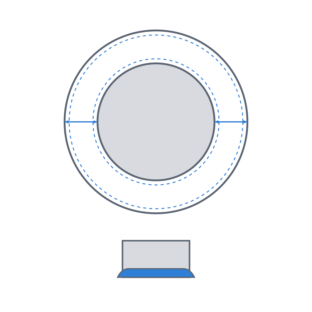
When you say "0.2 mm of clearance," you mean the gap on each side of the shaft, measured on the radius. That means the hole is 0.4 mm larger than the shaft in diameter: twice as much. It's the most repeated mistake in the whole craft: thinking in diameters, subtracting 0.2, and ending up with half the play you wanted; or reasoning per side, subtracting it twice, and ending up with double.
Always reason per side, because per side is how the material works: each wall lays down its own bead toward the gap independently, and the bead of the hole knows nothing about the bead of the shaft. Add the two sides together only at the end, when you convert to the diametral dimension you write into the model.
The hole closes in and the shaft swells out
A printer doesn't lay down perfect lines, and the net effect on any fit always goes the same way: holes come out small and shafts come out large. It pays to separate what happens to the hole from what happens to the shaft, because not every effect acts on the two parts equally.
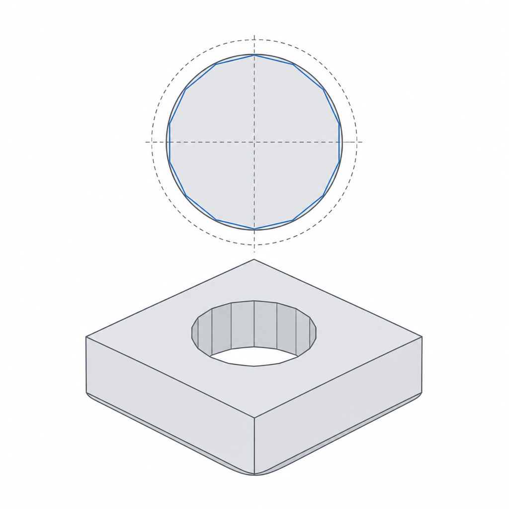
The dominant one is the bead width over a curved wall. The nozzle lays down a bead about 0.40–0.44 mm wide centered on its path. To make the wall of a hole, that path traces a circle smaller than the final hole, and the half of the bead that falls inward bites into the gap and narrows it. On a shaft the opposite happens: the path traces a circle larger than the final shaft, and the half of the bead that falls outward bulks up the contour and widens it. The same half-bead closes the hole on the inside and enlarges the shaft on the outside. That's why shaft and hole deviate in opposite directions, and why this effect dominates the rest.
The second is shrinkage on cooling, and here shaft and hole no longer go opposite ways: the plastic contracts by pulling toward its own center of mass, and that shrinks both. The ring of material around a hole contracts and drags the inner wall toward the center of the hole, reducing its diameter. In a solid shaft that same contraction pulls inward and shrinks the shaft, so there shrinkage works in favor of the fit: it partly offsets the bead's widening, though without canceling it, and the shaft still comes out large. On the hole, by contrast, shrinkage and bead width push in the same direction and add up.
The third is the squishing of the first layer, the elephant's foot, and it's a local effect, not a dimension shift along the whole joint. Layer one is printed slightly lower to stick to the bed, and the extra plastic squashes out to the sides; at the mouth of a vertical hole that narrows the first few tenths of height and leaves a tighter neck than the rest, while at the base of a vertical shaft it fattens only the start. It affects a neck of a few tenths, not the whole length of the fit (we develop this in Holes, pegs and first-layer squish).
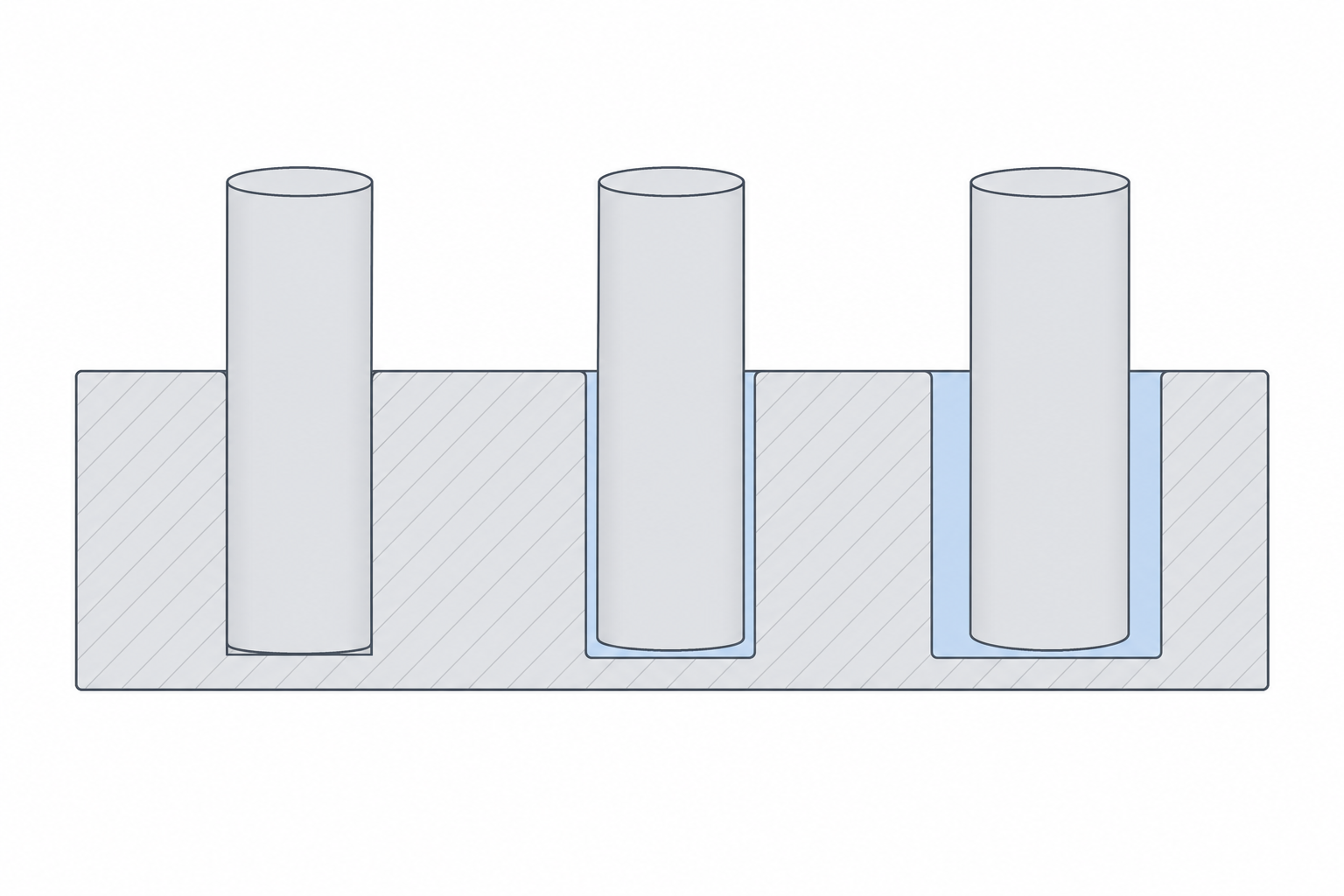
The consequence is the one that breaks mechanisms: a clearance of zero on screen is interference in the part. The two walls have moved toward each other before you do anything. That's why a mechanism is never designed with the nominal machining gap: you have to open it on purpose, with margin, knowing the printer will take a share.
Function decides how much clearance
How much gap is decided by the function, not by taste. These are reasonable starting values in PLA and PETG, per side and at normal quality (0.4 mm nozzle, 0.2 mm layer):
| What you want | Clearance/side | Typical example |
|---|---|---|
| Turns or slides freely | 0.20–0.35 mm | coarse pivot, hinge exposed to dust |
| Slides with no play | 0.10–0.15 mm | hinge, carriage on a guide |
| Positions and comes apart by hand | 0.05–0.10 mm | alignment pin, centered lid |
| Doesn't move (press fit) | −0.05 to −0.15 mm diametral | bearing seat, knob on a shaft |
Go up within the range when the joint has to tolerate dirt, paint, thermal expansion, or several layers of accumulated error along a train of parts; go down when you want precision and the joint is clean and short-travel. The value in the last row is negative on purpose and, unlike the rest, is given as a diameter: a printed press fit that holds needs tenths of interference, not the microns of a metal fit (we cover this in Interference without cracking).
The reasoning for why these families are what they are is in Choosing the fit: clearance, transition, interference; the numbers tuned material by material, in Real printed clearances.
Put all the gap in one part
When you distribute the clearance, do it asymmetrically on purpose: leave one part at its nominal size —usually the shaft, so you don't weaken it— and load all the gap by opening the other: the hole. The temptation is to center the fit, subtracting half from each side, but that leaves you two dimensions to move when something doesn't fit and no fixed reference.
Keep in mind that leaving the shaft at its nominal size on screen does not leave it at its real size: the process fattens it, so in the part the shaft already comes out oversized. That's why the hole has to absorb two shifts at once, its own shrinkage and the shaft's widening, and it's worth opening it to account for both.
With all the gap in the hole, you have a single dimension to touch and one intact part that serves as your reference. If it goes in tight, you enlarge the hole and reprint only that part, the cheap one; the shaft, which was already fine, is never touched again. It's the difference between iterating one part and reprinting the whole assembly on every attempt.
Measure your printer once and keep the number
No table replaces your specific machine. The material (PETG oozes strings and widens more than PLA), the nozzle, the speed, the temperature, the number of perimeters, and flow calibration easily move the figure by 0.2–0.3 mm between a well-calibrated PLA and an uncalibrated PETG — and one tenth is exactly the margin between "slides" and "seizes." With few perimeters, on top of that, a small hole can end up with no infill between walls and compress even further. The table above is the starting point; your real value comes from the part.
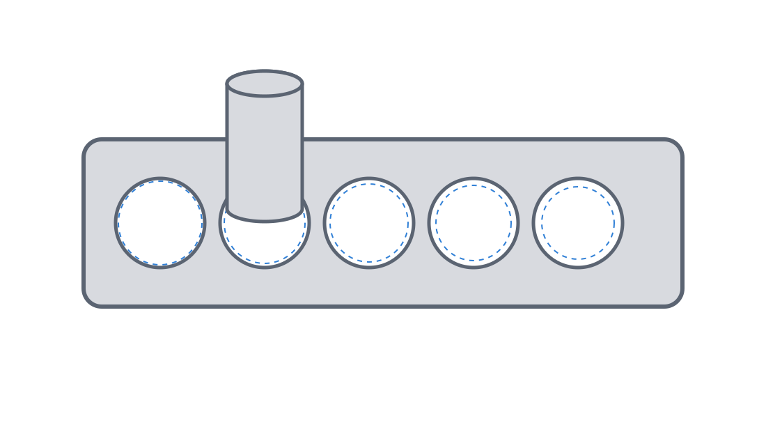
The honest way to find out is to print a tolerance tower: a series of holes on the same shaft (or of shafts in the same hole), each with a different clearance marked. You take it off the bed and test which one turns freely, which slides with no play, and which stays fixed. You note down those three numbers. From then on you stop guessing: that's your sliding gap.
Two conditions for the number to transfer. Orient the coupon the same way the final part will go: a hole printed horizontally comes out oval and collapsed at the top from the overhang, and its effective clearance has nothing to do with that of a vertical hole. And use it only on similar diameters: the bead error is absolute, but its relative weight and the curvature effects change with size, so a coupon of 6 mm shafts doesn't guarantee the same gap on a 20 mm or a 2 mm pivot. Within those two conditions, reuse the number across all your mechanisms until you change material or nozzle.
With that number in hand, the next step is to pick the right fit family for each joint before sizing it: Choosing the fit: clearance, transition, interference takes you from the function to the gap.