Cam and follower: any motion law from a profile
Almost any machine that opens, doses, or sequences movements hides a cam inside: a profile that turns at constant speed and, by its shape alone, forces a follower to rise, dwell, fall, and dwell again in a timed order. Nothing is more versatile for turning a uniform rotation into an arbitrary, repeatable motion. And almost everything that matters about a cam lies not in its size or its material but in the exact curve of its outline: that is where the motion law you'll get is written, millimeter by millimeter. Design that curve badly and you'll have a part that turns without seizing but pounds, vibrates, and always wears in the same spot.
The profile IS the motion law
The central idea is direct: the follower's displacement at every instant is dictated by the radius of the profile at that angle. If you call s(θ) how far the follower has risen when the cam has turned through an angle θ, the profile is nothing more than that same s(θ) added to the base radius and wrapped around the axis of rotation. That is why a cam is not drawn from the outside in, deciding "let it have this shape": it is designed the other way around. First you define the displacement diagram — the full cycle of rise, dwell, fall, and dwell, with how many degrees each segment occupies and how far the follower rises — and only then do you derive the outline that produces exactly that diagram.
That order is not a formality. The displacement diagram is where you set the kinematics, and the kinematics live in the second derivative. What the follower feels is not position but acceleration: that is where inertial forces, impacts, and noise are born. A rise segment at constant velocity seems the most natural thing — a straight ramp in the diagram — but that ramp starts and ends with a step in velocity, and a step in velocity is an infinite acceleration at each end. In practice that is a blow: the follower is flung out at the start of the rise and slams down at the end, and that pair of impacts per turn is what hammers the mechanism and wears it out.
The solution is to choose a motion law that smooths the ends. A cycloidal law brings acceleration to zero right at the start and end of each segment, so the follower starts and stops without a jerk. A harmonic law (the sinusoidal-profile one) is in between: smooth in velocity, but it enters and leaves the segment at maximum, not zero, acceleration, so when you splice a harmonic rise onto a dwell a finite jump in acceleration appears at the joint. It's acceptable at low speed but noisy at high speed. The practical rule is never to splice segments with a step in velocity, and as far as possible not with a step in acceleration either. Splice displacements, yes, but always think two derivatives above the curve.
When a cam beats a linkage
A cam has an advantage no linkage matches: it programs an arbitrary time sequence. If what you need is for something to open during exactly 90° of rotation, stay still for another 90°, fall over 120°, and rest for the remainder — or for three distinct motions to each happen in their own window of the cycle, perfectly synchronized to the same shaft — the cam delivers it directly and repeatably. A four-bar linkage or a crank-slider gives a fixed motion, usually sinusoidal or close to it, and you can't introduce dwells or freely redesign the shape of the rise. A cam can: the dwell is, quite simply, a segment of constant radius on the outline.
It's worth being clear about the other side of that versatility. The circular eccentric cam — a disc that turns on an off-center axis — is the trivial case, and precisely the one that takes advantage of none of the above: with a flat follower it gives an exact sinusoidal displacement, with no dwells, identical to that of a crank; with a roller or point follower, only approximately sinusoidal. If all you want is a smooth back-and-forth, an eccentric is easier to print and to balance than a free-profile cam. The arbitrary-contour cam is justified when you need what the eccentric can't give: pauses, asymmetry between rise and fall, or several timed actions in a single turn.
The pressure angle decides whether it turns or seizes
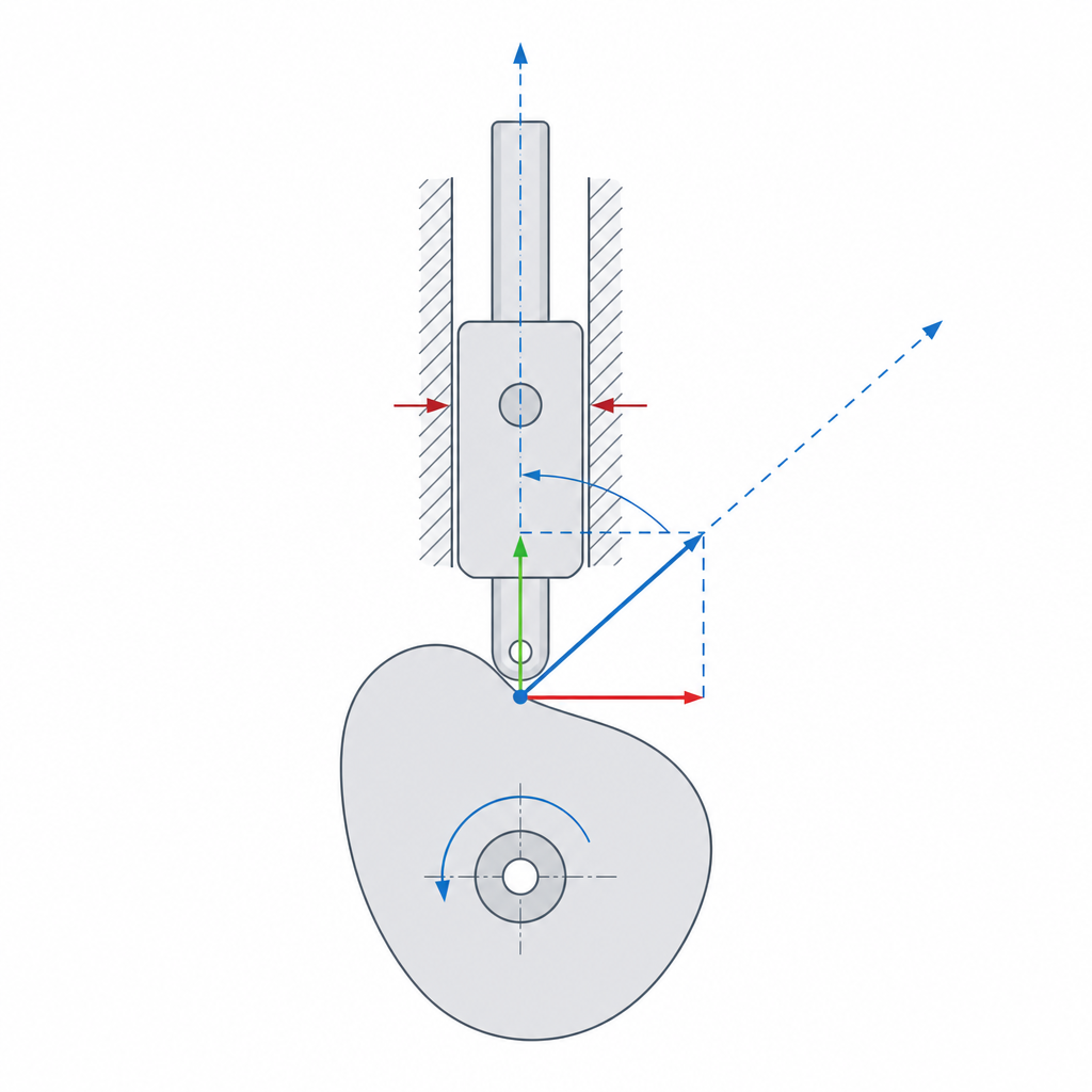
This is the parameter that ruins more working cams than any other, because it doesn't show up in the displacement diagram and only appears once the part is already turning. The cam pushes the follower along the normal to the profile at the contact point, but the follower can only move along its guide. The pressure angle is the angle between those two directions: between the direction in which the cam pushes and the one in which the follower can move. All the force that doesn't go in the useful direction resolves into a side component that presses the follower against its guide.
That side component is what seizes the mechanism. The larger the pressure angle, the larger the force pushing the follower sideways against its slide, the more friction it has to overcome, and the greater the risk that the follower wedges and stops moving even though the cam keeps turning. A high pressure angle turns a cam that works on paper into one that jams. For a translating follower with force closure — the most common case — the usual rule of thumb is to keep it below 30° throughout the turn; with an oscillating follower or with form closure the limit changes, but the criterion is the same: the more perpendicular the push is to the guide, the better.
What causes a high pressure angle is asking for too much rise in too few degrees: a profile that grows very fast relative to its size has very steep walls, and steep walls mean a high pressure angle. The cleanest design lever for lowering it is to increase the cam's base radius. With a larger base radius, the same follower rise is spread over a longer arc of contour, the slopes ease off, and the pressure angle drops. It costs a bigger cam, but it's almost always the right fix: rather than forcing the rise on a small cam, make it bigger. The second lever, only for a translating follower, is to offset the follower from the cam axis: the offset lowers the pressure angle on the rise at the cost of raising it on the fall (or the reverse), so it serves to shift the problem toward the segment that runs more lightly loaded.
Closing the pair: a cam pushes, but doesn't pull
There's a detail that gets forgotten until the mechanism fails at high speed: a cam only knows how to push. The contact between cam and follower transmits force in compression, outward from the profile; nothing pulls the follower back when the profile decreases. As soon as the follower has to track a profile that retreats, the only thing keeping it pressed to the contour is something pushing it against the cam. This is called closing the pair, and you have two ways to do it.
Force closure is a spring that permanently pushes the follower against the profile. It's the simplest and most common approach, but it has a ceiling. Liftoff doesn't happen generically "on the fall": it happens in the segments where the profile demands that the follower decelerate sharply — typically at the end of the rise, where the follower brakes to a stop, and at the transitions — not over the fall as a whole. In those zones it's the spring alone that has to impose on the follower the deceleration the profile asks for; if the spring is weak or the cam turns fast, there comes a point where the required inertia exceeds what the spring can deliver and the follower lifts off: it loses contact, flies free, and strikes the profile again further on. That liftoff is noisy, throws off the motion law, and pounds the part. The defense is a spring with enough preload and, above all, a law without sharp decelerations — the same cycloidal law as before, now in its decisive role.
Form closure eliminates the problem at the root: instead of resting the follower on an edge, you house a pin or a roller inside a slot cut into the cam face, so the slot wall pushes the follower from both sides. Rise and fall are controlled by positive contact, with no spring to depend on, and no liftoff is possible. The price is twofold. First, a slot needs clearance between the follower and its two walls so it doesn't seize, and that clearance causes a small knock when switching walls (crossover shock) each time the contact jumps from one to the other as the sign of the force reverses. Second, if you use a roller, the slot's two walls impose opposite directions of rotation on the rise and the fall: the roller can't roll cleanly in both senses, it has to stop and reverse, so in reality it slides under load against one wall for part of the cycle and wears there. Even so, for FDM — where a reliable metal spring is usually a separate part you'd rather not have — the slotted cam is often the cleaner option.
Printing it in FDM without the profile lying to you
Orientation is the first decision and the easiest. Print the cam flat on the bed, with its axis of rotation vertical, so the whole profile lies in the XY plane and the layers stack parallel to the plane of rotation. That way the contact surface against the follower is the side wall of the beads — the strong direction — and not the bonds between layers. A cam printed on edge leaves the profile crossing the layer planes, exactly where the follower's repeated contact opens and delaminates it; this is developed in Layer orientation for motion.
The second problem is specific to FDM and betrays free-profile cams in particular: faceting of the contour. An interesting cam is drawn with smooth curves — splines that embody your cycloidal law — but the STL-to-slicer chain reconstructs it with discrete segments in the XY plane. This isn't the stair-stepping between layers (that one is vertical, and the flat orientation keeps it out of the working profile): it's the contour curve reduced to a polyline. If the resolution is coarse, that smooth contour becomes a succession of facets, and each facet is a small change of slope that the follower perceives as a pulse: exactly the impacts you worked so hard to eliminate by choosing a smooth law, reintroduced by the mesh. A flawless cycloidal law is worthless if you print it with so few segments that the follower feels every one.
The real defense is upstream, in how you freeze the geometry. Export the profile with a fine chordal tolerance — or, better, in a format that keeps the curve instead of meshing it — because once the contour is faceted, the faceting is already frozen and no later adjustment recovers it. The slicer's arc-fitting (G2/G3) reconstructs arcs from the segments already present in the G-code and smooths the machine's motion, but it doesn't give back the original curve you lost by exporting coarse: it treats the symptom, not the cause.
At the cam-follower interface, a roller follower — a roller that rolls over the profile — drastically reduces wear compared to a flat or point follower, which rubs. In plastic against plastic, where sliding friction files the profile down fast, rolling instead of dragging makes the difference between a cam that keeps its law for many turns and one that flattens in the zone of maximum contact; and the pair of materials in contact matters as much as the choice of roller, because PLA, besides being filed down, cold-flows under sustained load. Watch two more things on the roller. Its fit on its pin, like any printed pivot: not so tight it won't turn, not so loose it wobbles; the criterion is explained in Tolerances for moving parts. And a geometric limit that ruins the law without warning: if in some concave segment the radius of curvature of the profile is smaller than the roller radius, the roller doesn't fit in the valley and the contour gets undercut (undercutting). However finely you print, the cam won't reproduce its law there. The cure is the usual one: a smaller roller or a larger base radius that eases the concavities.
The three ways a printed cam dies
It's worth naming the three failures so you can anticipate them. The first is wear or flattening of the profile in the zone of maximum contact: the point of the contour where the force is greatest — typically the steepest part of the rise — gets filed down turn after turn, the motion law degrades, and the follower starts arriving late or falling short. It's the slow mode, and you fight it with a roller follower, a sensible pairing of materials, a well-printed profile, and, if needed, a bigger cam that spreads the contact.
The second is follower liftoff, which is always a problem of negative acceleration, wherever it falls in the cycle: a spring too weak for the rotation speed, or a law with a sharp deceleration at the end of the rise or at a transition, makes the follower lose contact, fly, and strike. You cure it by raising the spring preload, smoothing the curve in the zone of maximum deceleration, or switching to form closure. The third is seizing from a high pressure angle, already seen: the side component wedges the follower in its guide and the cam jams even though the motor still has torque to spare.
All three are anticipated in design — the curve, the base radius, and the closing of the pair — far better than they are repaired in the already-printed part. A well-reasoned cam is, almost always, one that never gets to fail in any of the three ways.