Compliant bistables: buckled beam, flexible four-bar, and negative stiffness
A switch that clicks, stays put, and won't move back to the other side until you push it again: that's a bistable, and nearly every one you touch day to day pulls it off with a metal spring and a detent. In FDM you can get the same behavior from a single part, with no pins, no separate springs, and no assembly. It exploits the fact that a thin beam forced to bend stores energy and only ever wants to sit in two places. The trick is buckling: putting that beam right on the edge of snapping from one side to the other, then using geometry to control how hard that snap is. It all comes down to the initial curvature, the slenderness of the beam, and a few tenths of a millimeter of thickness your printer never lays down exactly where you drew it.
Why a curved beam has two states, not one
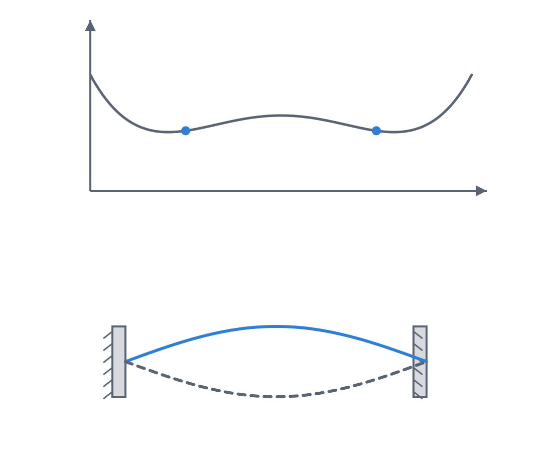
Take a thin strip, hold it by both ends, and bring them slightly together: the strip won't stay straight and compressed; it bows to one side. You've buckled the beam. Now press the center of the arch toward the other side: at first it resists, then at some point it gives way all at once and settles arched toward the opposite side, where it stays. You've just gone through a snap-through (an abrupt jump between two shapes), and the strip is bistable: it has two stable arched shapes and no intermediate one that holds.
The reason is about energy. A pre-compressed or initially curved beam stores elastic energy, and that energy, plotted against the displacement of the center, has not one well but two, separated by a hump. Each well is a stable state: push a little and let go, and the beam returns to the bottom of the well. The hump between them is the energy barrier, the peak force you have to overcome to push the beam to the other side. Until you reach the top, the part resists; the moment you pass it, the stored energy finishes the trip and is released as the click. That layout—two wells and a barrier—is what separates a bistable from a plain spring, which has only one well and always pushes you back to the same place.
What's interesting for design is that the shape of that energy curve isn't fixed: you set it with geometry. A larger initial curvature or a more slender beam raises or lowers the central hump, and with it the trigger force—and how firmly each state settles into its well. A barely curved beam gives a soft click and two weakly defined states, easy to switch by accident; a well-arched one gives a crisp trigger and positions that hold. Designing a bistable is, ultimately, sculpting that hump so the click costs exactly what you want it to cost.
From the rigid four-bar to the compliant one
Buckling a beam isn't the only way to get two states. The other major family comes from taking a classic pin-jointed mechanism—the four-bar linkage—and replacing its pins with flexures. In a classic four-bar, four links joined by four pivots define a path; in the compliant four-bar (flexible-joint), those pivots vanish and thin flexing segments take their place, so the entire mechanism is a single printed body. There are no pins to assemble, no clearances to calibrate, no play that creeps in with wear. The kinematics live in the flexibility of the material, not in parts sliding against each other.
When that flexible four-bar is sized so that, over its travel, some of its flexures have to pass through a state of maximum deformation before relaxing to the other side, the whole mechanism becomes bistable in a single part: it has two configurations in which the flexures are at minimum energy and an intermediate, tensed position that doesn't want to hold. It's the same energy barrier as the buckled beam, but spread across several flexures instead of concentrated in a single strip. That gives more freedom to set where each stable state lands and what path the part follows between them.
Out of this comes a third idea, subtler and more useful still: negative stiffness. The normal stiffness of a spring is positive: the more you deform it, the harder it pushes back. But a buckled element, while it crosses its barrier, does the opposite: it pushes along with the motion, helping you keep displacing it. That is negative stiffness, and an equilibrium with net negative stiffness won't hold. The key is to combine a positive-stiffness element with a carefully matched negative-stiffness one: if the push-along of one cancels the push-back of the other, the net stiffness goes to zero and you get a near-constant-force mechanism that opposes the same effort across the middle of its travel instead of stiffening at the end. If the cancellation is partial, you soften the stiffness without zeroing it, which is exactly what a vibration isolator asks for, or a preload that mustn't change with displacement.
When a single-body bistable is the right call
You reach for it when you want a part to hold a state—to remember where it was set—without assembling anything. A monolithic switch or clip that toggles with a firm click and stays where you leave it is the textbook example: one printed part, zero screws, zero springs to buy, zero assembly. A latch that has to be clearly open or clearly closed—and never halfway—gains a lot from bistability, because the energy barrier penalizes intermediate positions and pushes the part to commit to a state.
Beyond the click, the family does two things a normal spring can't. One is near-constant force: a dispenser that always pushes with the same effort, a closure mechanism that doesn't stiffen at the end of travel, a preload that holds even as the part moves. The other is stiffness cancellation to isolate vibration or support a load with a flat effort. In all of these the same thing is true: you don't want pins or separate springs; you want the part to be its own mechanism. If your design can already be monolithic, a compliant bistable saves you the whole assembly step and eliminates the pivot clearances detailed in Interference without cracking.
Layer orientation decides whether it works or fractures
This is where FDM imposes a hard constraint. A beam that buckles works in bending, and bending means stretching the outer fiber of the arch. In a printed part, the direction in which that tension is most dangerous is between layers, where the only thing holding the material is the weld of one bead to the next. The rule isn't just "make the beads run along the beam": it's that the bending must stay contained in the plane of the layers. That is, the beam must flex in its own print plane, with the bending axis in the XY plane, so that the bending tension runs through the material along the beads and never pulls on the interface between one layer and the one above it.
If you print it so that the bending is perpendicular to the layers—on edge, or laid flat but flexing up and down—each flex pulls directly on those bonds and the beam delaminates: it opens between two layers like a clean crack, almost always long before it tires from real fatigue. You won't have made a bistable; you'll have drawn a fracture line. Lay the beam flat on the bed and orient the mechanism so the buckling travel lives in the XY plane whenever the geometry lets you; the reasons behind this anisotropy and how to orient each kind of flexure are worked out in Layer orientation for motion.
And choose the material thinking about how much that outer fiber is going to stretch. PLA is stiff and brittle: it stretches little before breaking, so a PLA flexure tolerates very little deformation—on the order of 0.5 to 1% working strain before cracking—and snaps clean. PETG, PP, and nylon stretch several percent before failing, and that's why they're the materials of compliant design: they take the buckling travel with margin and survive repeated cycles without cracking. Each has its own processing pitfall, though: PP combines excellent living-hinge properties with poor layer adhesion and severe warping, exactly what punishes a flexure that loads the interfaces most; nylon is hygroscopic and, if it absorbs moisture, drops in modulus and changes the feel of the click. Size the slenderness—the ratio of beam length to thickness, typically on the order of 10 to 30 to 1—so that the peak deformation in the most stressed state stays below the material's fatigue limit, not just below its single-cycle break: a bistable that survives the first click but fails on the hundredth is no good.
The three failure modes, and why a tenth of a millimeter changes everything
A compliant bistable fails in three ways, and it pays to know which one you're looking at. The first is brittle fracture of the beam in its most stressed state, typical of PLA: the outer fiber exceeds the elongation the material can take and the flexure snaps, usually at the point of maximum buckling curvature or on the most demanding click. The second is creep: under the sustained stress of staying arched in one state, the beam slowly flows, the curve gradually flattens over time, and the energy barrier lowers until one day the mechanism stops being bistable and settles into a single position, with no click. Every FDM thermoplastic creeps at room temperature under load, and PLA, stiff as it is, is among the worst at creep: stiff is not the same as stable under permanent load. The third is fatigue: after many back-and-forth cycles, microcracks grow in the most loaded zone and the beam eventually gives way even though you never took it to the limit in a single motion. Here the material rules: a well-oriented PP can give 10⁴ to 10⁶ cycles, while a PLA at appreciable working strain falls orders of magnitude short.
All three share an uncomfortable sensitivity: the behavior depends enormously on the actual printed thickness of the beam. The bending stiffness of a beam grows with the cube of the thickness, so the trigger force scales hard with that dimension: a flexure you drew at 1.0 mm and the printer laid down at 1.2 mm—two tenths, the kind of drift any FDM setting shows—isn't 20% stiffer; it's on the order of 70% stiffer, because 1.2³ against 1.0³ comes close to double. Note: that cube is the rule for pure bending stiffness (EI ∝ t³); in a bistable's trigger, the click force also depends on the initial curvature and the slenderness, which are usually set as multiples of the thickness itself, so the exact relationship isn't a clean t³. But the moral holds: those two tenths can turn a soft click into one that takes real effort to overcome, or push the peak stress above the fatigue limit and drop you straight into the first failure mode. Slenderness is not a "tune it later" parameter: it's what governs both the force and the life of the part at once.
| Mode | What you see | Root cause | How you head it off |
|---|---|---|---|
| Brittle fracture | The beam snaps clean, often on the first demanding click | Low-elasticity material (PLA) or insufficient slenderness; peak stress above the break point | More ductile material (PETG, PP, nylon) and a more slender beam to spread the deformation |
| Creep | The curve flattens over time and bistability is lost | Sustained stress in the rest state; all thermoplastics creep, PLA among the worst | Design the wells near minimum energy; choose the less-stressed state as the rest position |
| Fatigue | Gives way after many cycles without ever being pushed past its limit in a single motion | Working deformation above the material's fatigue limit | Lower the working strain; well-oriented material with good bending fatigue (PP) |
Print a prototype before you trust a single number
For all these reasons, a compliant bistable isn't finished on screen; it's finished on the bed. The effective elastic modulus and yield strength of an FDM part aren't the ones on the material datasheet, because they depend on the infill, the number of perimeters, the extrusion temperature, and the orientation you printed it in. A beam with two perimeters and light infill behaves very differently from the same beam printed solid, and no table will give you the exact trigger force of your part on your printer.
The honest way to finish it is to print the bistable and measure the click by hand, the same way you calibrate any other setting. If it triggers too soft, thin the beam down or raise its initial curvature; if it costs too much or cracks, thicken or lengthen it to spread the deformation. And since one tenth of a millimeter of thickness radically changes the result, it's worth printing two or three variants with the slenderness stepped in the same batch and keeping the one that triggers the way you want. That prototype is worth more than any closed-form calculation: it gives you the real number, with your material, your perimeters, and your orientation baked in. From there, reuse it as long as you don't change filament or nozzle.
If your bistable ends up being a snap fit that has to stay closed and carry load without releasing, the reasoning for how far you can push the geometry without cracking the part is the same that governs any printed press fit, and it's worked out in Interference without cracking.