Geneva drive (Maltese cross): one step per turn
A motor spins without stopping; you want the wheel to advance one step, lock in place, and not budge until the next one. That is exactly the contradiction the Geneva drive resolves: it turns continuous rotation into indexed advance. A pin mounted on the driving disc enters a slot in the driven wheel — the cross, a four- or six-armed star — drags the wheel through a precise step, then exits; for the rest of the turn, a concave arc on the driver hugs the contour of the cross and holds it locked with no brake of any kind. It is the classic indexer of film projectors, carousels, and camera drums. It is one of those parts that, in FDM, either works beautifully or fails at the mouth of the slot, with nothing in between. Everything rides on two things: the entry has to be tangent, and the pin must not break.
One turn in, one step out, then a dwell
The beauty of the mechanism lies in splitting each turn of the driving disc into two very distinct phases. For a fraction of the turn — and only during that fraction — the pin on the driving disc is inside one of the cross's slots. While it is inside, it pushes: the driven wheel turns. The moment the pin exits the far end of the slot, the wheel stops dead and stays motionless until the pin completes the rest of its turn and enters the next slot. A continuous input rotation thus produces a jerky advance at the output: step, dwell, step, dwell.
The step size is set by the number of slots. With n slots spaced evenly, each engagement advances the wheel by exactly 360°/n: a four-slot cross indexes in 90° increments, a six-slot one in 60° increments. And there is a ratio here worth pinning down before you draw anything, because it is counterintuitive. The fraction of the driver's turn during which the wheel is moving is 0.5 − 1/n: with four slots, 25% of the turn moves and 75% is dwell; with six, 33% moves and only 67% rests. In other words, the more slots, the larger the fraction of the turn the wheel spends moving — and the less of the turn is left for dwell. The four-slot cross is the one that rests longest between positions.
That makes the number of slots a trade-off, not a dial you simply turn up. If what you want is a long, well-defined pause between positions — the time a frame stays still in front of the lens — you want fewer slots, with three as the practical limit, which already indexes abruptly. What you gain by adding slots is smoothness: the step is shorter, the acceleration of each engagement is lower, and the mechanism runs finer at high speed. More dwell or smoother motion: pick one, because you cannot have both at once.
What makes this a mechanism and not a hammer blow is how the pin enters and exits. If the geometry is well proportioned, the pin enters the slot with tangential velocity: at the instant of engagement, its motion is aligned with the slot, so the wheel starts from zero speed with no lateral component. The wheel reaches its peak angular velocity around mid-step and slows back to zero just as the pin exits. Velocity is continuous at both ends, and that is why there is no velocity shock at the start or the stop.
Tangency is not optional: the pin enters head-on or it hammers
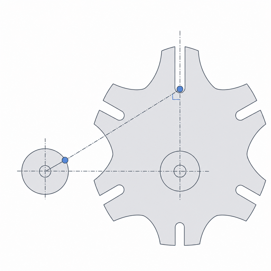
The heart of the design is a single geometric condition, and if you get it wrong you do not have a Geneva drive — you have a rattle. The pin has to enter and exit the slot tangentially, meaning with its path aligned with the slot's direction at the exact moment of engagement and disengagement. For that to happen, three things have to be true at once, and all three are coupled: the cross's slots must be radial — pointing to the wheel's center — the center distance has to be set for the number of slots, and the radius at which you mount the pin on the driver is fixed by the first two.
The clean way to reason about it: at the instant of engagement, the line joining the two centers, the pin's radius on the driver, and the cross's slot form a right angle. The dimensions fall out of that right triangle. If you call the center distance C, the pin's crank radius is R = C·sin(180°/n) and the cross radius is r = C·cos(180°/n), with R² + r² = C². So radial slots and correct centers are not enough: the radius where you set the pin is not free, it is dictated by C and n. The pin then meets the slot head-on, sliding inward with no lateral component. If you push the centers apart or bring them closer than their correct value, that angle stops being a right angle, R no longer matches, and the pin arrives at the mouth of the slot moving crosswise. The first consequence is an impact against the entry flank: the wheel does not start smoothly, it starts with a kick. In FDM that shows up immediately, because that repeated impact pounds exactly the most exposed corner of the whole part.
The locking arc: what holds the wheel between steps
If you had only the pin and the slot, the wheel would be left loose the moment the pin exited: any inertia or vibration would spin it freely and you would lose the indexed position. What prevents that is the other half of the driving disc: a concave locking arc carved into the driver that, throughout the stretch where the pin is out, hugs the convex profile between the arms of the cross. While that arc is in contact, the wheel cannot turn either way: it is mechanically locked, with no need for a spring, brake, or detent. That is why a Geneva drive holds its position on its own, and why it is so good at indexing: between steps, the position is held by geometry, not by friction.
There is one detail that often gets left out, and it decides whether the mechanism turns or seizes: that arc cannot be a full circle. Right where the arm of the cross is about to pass to enter the engagement, the driving disc carries a clearance relief — a crescent cut around the pin, tangent to its path. Without that relief, the convex contour of the cross has no way out of the arc and the wheel stays locked forever: the pin pushes against a cross that cannot turn. The relief frees the arm at the exact instant of engagement and closes the lock again the moment the pin exits. If you model the lock as a continuous arc without that notch, the mechanism seizes on the first attempt to advance.
The other point is the clearance between the locking arc and the contour of the cross. You want the arc to hold firm — so the wheel does not wobble between steps — but without rubbing under pressure, because then the motor has to overcome that friction throughout the entire dwell phase and the mechanism binds. It is the same trade-off as any printed sliding fit, only applied to a long arc instead of a pivot: too much margin leaves the wheel with play — you hear the rattle again every time something jostles it — and too little turns the lock into a brake. Size it as a clean sliding fit, allowing for the fact that the arc gap tends to come out a touch narrower than you draw it — measure on your printer and compensate — as covered in Tolerances for moving parts.
Print flat and reinforce the pin
In FDM, print orientation decides the failure mode, and here there are two surfaces that take all the load: the slot walls, which receive the push of the pin, and the locking arc, which holds the wheel still. Print both the driving disc and the cross flat, with their profiles lying in the bed's XY plane. That way the slot walls and the arcs are formed by continuous beads running along the contour, and the pin's contact works along the beads, not between layers. If you printed the cross on edge, the slot walls would delaminate: the push of the pin would pull right on the weak plane between layers and the mouth of the slot would open up like a zipper after a few turns. This is the same logic as Layer orientation for motion: put the strong plane where the load is.
The pin is the critical point, and it is worth confronting directly. The entire indexing force — starting the driven wheel from rest, accelerating it, braking it — passes through that single pin, and over a small contact surface at that. A pin printed in plastic, especially upright on the bed, concentrates that load at one point and snaps: it is the most typical failure of the mechanism. The real fix is to stop the pin from being the weak point. Make it sturdier — generous in diameter, with a good fillet at its base to spread the stress — or, better, embed a metal pin: a length of steel rod or a bolt housed in the driving disc takes the indexing indefinitely and eliminates breakage at the root. How to house that metal in the printed part without it working loose or cracking the plastic around it is covered in Embedded hardware: magnets, bearings, and inserts.
| Decision | Criterion | If you get it wrong |
|---|---|---|
| Number of slots | Sets the step (360°/n) and the dwell-to-motion ratio (0.5 − 1/n in motion) | Wrong step size or dwell ratio; fewer slots give more dwell, not less |
| Center distance C | Slot perpendicular to the line of centers at engagement; R = C·sin(180°/n) | Pin enters crosswise, strikes the mouth of the slot |
| Clearance relief on the driver | Crescent cut that frees the arm at engagement | Without it the cross cannot leave the arc: permanent lock |
| Slot clearance | Tight sliding fit, no rattle | Wheel wobbling between steps, or a seized slot |
| Locking arc clearance | Holds firm without rubbing tight | Play between steps or a permanent brake |
| Print orientation | Profiles flat in XY | Slot walls delaminate on the first push |
| Pin | Sturdy or embedded metal | Snaps when it concentrates the whole advance load |
Three failures, and where each comes from
When a printed Geneva drive does not work, it is almost always one of three failures, and all three come from the geometry, not from bad luck. The first is the strike at the mouth of the slot: if the entry is not tangent — centers wrongly spaced, crank radius off, or slots not radial — the pin hits the entry flank on every step, and that repeated impact chips and wears the most exposed corner of the cross until the slot loses its shape and the engagement goes slack. It is fixed in the model, squaring C, R, and n together, not by sanding the part afterward.
The second is play between steps: if the fit of the slot or the locking arc came out loose, the wheel is not firmly locked when the pin is out, and any vibration or inertia makes it wobble around its indexed position. You lose precisely what you came for: a discrete, repeatable position. The cure is to tighten those margins toward a play-free sliding fit, remembering that the printed gap usually comes out tighter than drawn.
The third is pin breakage, and you already know where it comes from: it concentrates the entire advance force at one small point, and a printed plastic pin — especially an upright one — will not take it indefinitely. Make it sturdier, round its base, and when the indexing is demanding or the mechanism is going to run many turns, embed metal. Of these three, the pin failure is the only one that plastic, on its own, cannot fully resolve: the other two you close with geometry and clearance; this one you resolve, almost always, by letting steel do the pushing.
If you are going to embed a metal pin — and for nearly any real application it is worth doing — house it well: how to size the bore, orient the part, and keep heat or interference from cracking the plastic around the metal is covered in Embedded hardware: magnets, bearings, and inserts.