Conical twist lock: locking by cone friction
A male cone enters a female cone, you push it home or give it a quarter-turn, and the two parts lock together with no play, perfectly aligned, and nothing works itself loose. There's no thread, no press-fit, no screw: just two conical surfaces clamping against each other. It's the Morse taper you already know, the same one that holds a tool in a lathe spindle by geometry alone, and it prints well as long as you understand what its grip depends on. It holds for one specific physical reason and fails for three others, all worth naming before you model anything.
Why a cone self-locks
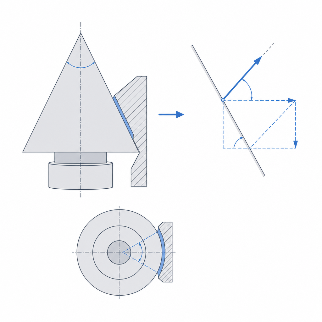
The key is the angle. When you push a male cone into a matching female one, the contact is neither a line nor a ring: it's the entire lateral surface of the cone pressing against its mate. That surface generates a distributed normal force, perpendicular to the cone wall at every point. Here is the physics that decides everything: the normal force splits in two. One pushes axially, outward, trying to expel the cone; the other is the one friction acts on to hold.
If the half-cone angle —the one the cone wall makes with its own axis— is smaller than the friction angle of the material pair, the coupling is self-locking: the axial component pushing the cone outward is smaller than the friction force opposing its escape, and the cone won't release on its own no matter how hard you pull it straight out. It's the same reasoning as a fine-pitch screw that doesn't loosen under vibration: the geometry sits below the threshold where friction stops being in charge. That threshold is physical and depends on the friction coefficient: with plastic against plastic, μ runs from about 0.2 to 0.4, which puts the friction angle —arctan μ— between roughly 11 and 22 degrees. Below that half-cone angle, the cone self-locks; above it, it starts ejecting itself.
That leaves you plenty of margin, and the comfortable range for a printed cone sits at the low end: 2 to 8 degrees of half-cone. Not because it stops gripping at 9 or 10 degrees —with plastic it's still within the self-locking range— but because small angles give progressive seating and a generous clamp without crossing into impossible-to-extract territory. Below 2 degrees it grips so hard it's tough to separate by hand; that's exactly what a lathe's Morse taper does, with a half-angle of barely 1.5 degrees, designed never to release without a drift.
Material and finish decide the friction angle
The whole self-locking story rests on μ, so the material isn't a detail: it's the variable that moves the threshold. PETG prints rougher and tackier, with high μ, and self-locks at larger angles than a smoother, more slippery PLA. TPU is a case of its own: it grips enormously, but its flexibility changes the rules. Two cones identical in dimensions can behave very differently just because of the filament, so measure the grip in the part's actual material, not whatever happens to be loaded.
The finish pulls in the same direction. A smooth conical wall, well cooled and without over-extrusion, makes uniform, predictable contact; a wall with whiskers, strings, or irregularities touches in fits and starts, and the effective μ varies from one assembly to the next. And as you'll see below, print orientation is what most decides that finish.
Self-centering, with no radial play
A cylindrical press-fit holds, but it carries all the radial clearance you gave it: the shaft can sit off-center inside the hole by half the clearance, and if you tighten to eliminate it, you put the wall in tension and risk cracking it — the problem worked through in Press-fits that hold. The cone solves both at once. As it seats, the two conical walls meet and center themselves: the cone pair eliminates the radial play and aligns the two axes automatically, because any offset makes one side of the cone touch before the other, and the geometry corrects it as you keep pushing.
That's exactly what you want when two parts have to end up coaxial: a spindle and its accessory, a handle and its tool, an interchangeable nozzle on its seat. You don't depend on the tolerance of a hole for two things to line up; the shape does it. That said, do not expect infinite stiffness under a lateral load: the cone's resistance to bending moments grows with the conical contact length and with the stiffness of the plastic, so a short cone printed in FDM flexes and wobbles if you load it sideways. If you need lateral firmness, lengthen the engagement before tightening harder.
Taper forgives the tolerance a cylinder punishes
Here's the most important practical difference from a cylindrical fit, and the one that makes a printed cone easier to get right than it looks. In a cylinder, diameter is everything: a tenth too much and it wobbles, a tenth too little and it will not go in, or it cracks. The margin between "loose" and "stuck solid" is a few tenths, the very ones your printer varies from part to part, which is why Tolerances for moving parts insists you measure your machine before trusting a number.
In a cone you don't calibrate the diameter: you calibrate the seating depth. If the male cone comes out a bit undersized, it doesn't stay loose; it simply seats a little deeper until the two surfaces touch, and the lock is the same. The taper turns a diameter error into a depth error, and the angle governs that conversion: the axial displacement is Δz = Δd / (2·tan α), with α the half-angle. At 4 degrees, tan α ≈ 0.07, so a tenth of a millimeter of diameter translates into about seven tenths of axial travel; at 8 degrees, into about three and a half tenths. The amplification is real but modest at the angles in this range: count on fractions of a millimeter of axial margin, not whole millimeters, unless you drop to very small angles.
Even so, that margin is more than enough to absorb FDM scatter. In a straight fit, the same error leaves you stranded between two steps of your calibration; in a cone, it only shifts where the part comes to rest. Model the male cone slightly shorter than the female cavity, let it seat on friction and not on the bottom, and forget about the exact diameter.
Print it standing up, or you lose the grip
Everything above assumes the two conical surfaces are smooth and touch across their full extent. FDM can wreck that premise with a single orientation mistake. Print the cone vertical, with the cone axis coinciding with the printer's Z axis. That way each layer is a circle and the conical wall comes out as a surface of revolution, stepped only in fine increments of the layer height.
Lay it down and you ruin it. With the cone axis horizontal, the cross-section stops being circular: deposition turns each slice into a slightly elliptical profile with flat faces, and the inclined surface fills with layer stepping. The cone is no longer a surface of revolution, so it no longer mates against its partner across its full extent: only the crests touch, the normal force concentrates on a few lines, and the effective friction drops. The cone that should self-lock loosens because there's no longer a complete surface to rub. It's the same anisotropy-and-finish logic that runs through Layer orientation for motion, applied here not to strength but to friction: layer orientation decides not only how much the part holds, but how much it grips. A cone that works standing up may grip nothing lying down, even though not one dimension has changed.
Printing it standing up is the necessary condition, but it doesn't leave the wall perfect. The axial stepping when vertical is proportional to 1/tan α, so the smaller the half-cone angle —exactly the ones self-locking prefers— the shallower the wall and the more pronounced the step. The most self-locking cones are precisely the ones that leave the worst finish standing up. Compensate with a fine layer height in that zone; it's the cheap way to recover the continuous contact that the grip depends on.
When to use it (and the three ways it fails)
The conical lock is the answer when you want a joint that is demountable, self-centering, and vibration-proof: handles that swap out, interchangeable nozzles, spindles that tools couple to, any pair of parts that must end up coaxial and firm but that you will later separate by hand. If you need a positive lock on top of the friction —one that can't pull out even if friction fails— combine it with a quarter-turn: a bayonet or a pair of pins that, once the cone is seated, lock it against pull-out. The cone gives the centering and the clamp; the quarter-turn gives the safety catch. One caveat: that printed bayonet needs its own clearance, and if you tighten it to the point that it constrains the conical seat, it reintroduces the radial play the cone had eliminated. Let the catch lock the escape, but let the cone rule the centering.
It's worth knowing the three ways a printed cone fails you. The first is over-driving: if you push a very self-locking cone in too hard, you enter the regime of a true Morse taper, where the tool won't come out without a drift. With plastic this gets worse because of creep, which cuts two ways you should not confuse. Under sustained load, an over-driven cone settles over time and gets even harder to remove; but that same creep relaxes the contact stress in a cone held under constant preload, reduces the normal force, and, over months, loosens the grip. Tighten just enough to grip, without driving it home. The second is surface wear after many cycles: each assembly scrapes away a little of the plastic walls, the cone seats a little deeper each time, until the fit loosens; it's the same deterioration as any plastic joint subjected to repeated rubbing against its mate, and the reason a frequently-assembled cone is a candidate for a metal seat bushing. The third you've already seen: the friction loss from layer stepping of a wrong orientation, which is not a usage failure but a printing one, and is avoided by printing it standing up.
If you do not want to take it apart but to fix it permanently with radial interference, the reasoning shifts from taper to controlled interference and the risk of cracking the wall — covered in Press-fits that hold.