Notch and cartwheel flexures: thinning down to make a pivot
Almost every joint you design solves rotation with two parts and a gap between them: a shaft, a hole, and the clearance that decides whether the motion is smooth or seizes. But there is another way, and sometimes it is the right one: instead of adding a pivot, you create one by removing material. You thin the plastic down to a narrow strip, and that strip becomes the only place the part can bend. No shaft, no hole, no clearance to dial in, no assembly to fit: the joint comes off the printer in one shot, monolithic, and rotates exactly on the line you chose to thin.
In exchange you give up almost all the travel. This is not a hinge; it is a precision pivot that moves a few degrees, and everything that matters about it fits inside the thickness of that strip and the radius with which you blend it into the rest of the part.
Why thinning concentrates the bending
The mechanics are beam mechanics, and they contradict the intuition of anyone who thinks a thinner part is simply a weaker part. When a solid bends, the bending stiffness of each section grows with the cube of its thickness. That means halving the thickness of a section makes it eight times more flexible, all else equal: not twice. Spread that difference along a part — a thin strip between two blocks that keep their full thickness — and the result is dramatic: the thick material on either side of the notch barely registers the load, and all of the curvature piles up in the thin stretch. You have manufactured a pivot without ever leaving the continuous geometry of the plastic: you have only told the solid where it is cheap to bend.
A notch flexure is exactly that: a cut — on one face or on both — that leaves a thin strip joining two rigid blocks. All of the rotation lives in that strip, and for small angles it behaves like a fixed-axis pivot located at the center of the notch. It is the simplest flexure there is and the easiest to print: one recess and nothing more.
The problem shows up when you actually make it rotate. The center of rotation of a simple notch does not stay put. The instantaneous center of rotation sits roughly at the centroid of the minimum section, and that position migrates with the angle through the geometry of the bending itself: the point the part pivots about shifts relative to where it sat at rest. For a stop, a latch, or a tab moving a few degrees, that is irrelevant. For a positioning stage where you measure displacements in hundredths of a millimeter, that drift is an error that feeds straight into your reading.
The cartwheel fixes the center
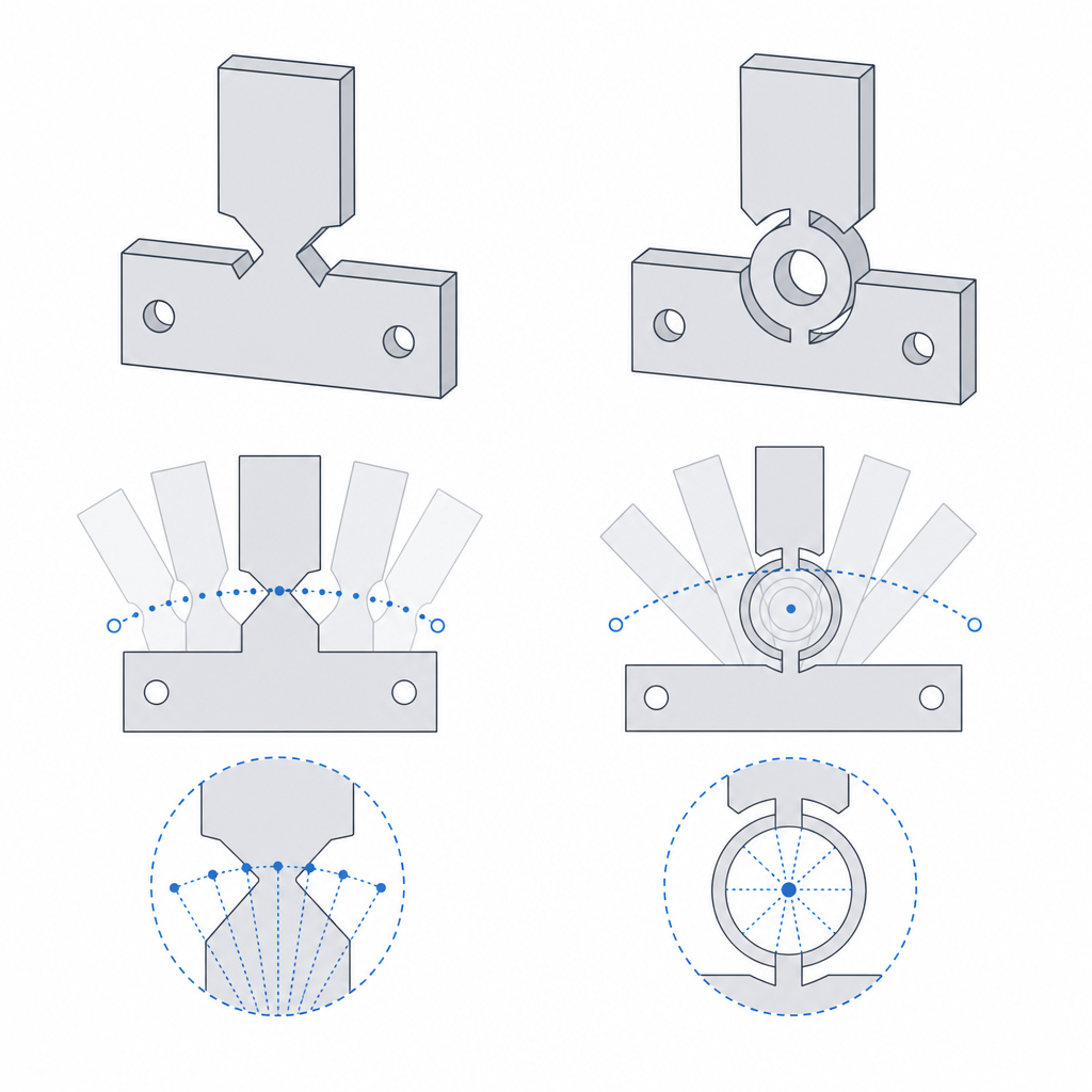
The cartwheel attacks precisely that drift of the center. Instead of a single straight strip, it arranges two thin blades that cross at the center of the pivot, like two spokes of a wheel meeting at the axle. Each blade flexes and drags its own center, but the two are symmetric about the crossing: the drift one introduces is opposite to the drift the other introduces, and because they share the crossing point the two largely cancel. This is not an anchoring by tension; it is a geometric compensation of the drift. The result is a much better-centered axis of rotation, with a residual drift of higher order in place of the first-order wander of the simple notch.
You pay for that precision in complexity. The cartwheel has two thin blades instead of one strip, a crossing to model and blend, and more delicate surface that can fail in the print. The decision rule is direct: if all you need is for something to rotate a few degrees and it does not matter exactly which point it pivots about, the simple notch is enough. If the center of rotation is a dimension that enters your calculations — a motion amplifier, a focusing stage, a compliant mechanism (one with a flexible body) where the kinematics must be predictable — the stability of the axis justifies the cartwheel.
The thin strip is the plane FDM breaks first
This is where a printed flexure is won or lost; not in the beam mechanics, which hold for any process. An FDM part is a stack of beads welded between layers, and that weld between layers is the weak plane: it holds much less than the material along the bead (this is developed in Layer orientation for motion). Your flexure concentrates all of the part's deformation in one tiny strip. If that strip has the layer-bond plane right where the bending pulls to open it, you are not flexing plastic: you are opening a crack between two layers, cycle after cycle, until it delaminates.
The rule that truly governs is the orientation of the layer plane relative to the bending plane: the layers must end up parallel to the wide face of the strip, so that the tension in the outer fiber runs within a layer and not across the interface between layers. Lay it flat and make it flex in the plane of the layers. A flexure printed on edge, with the layers stacked in the direction the strip bends, is a joint that comes pre-cracked from the factory: it snaps cleanly between two layers, almost always in the first few cycles. Having the beads run along the strip is necessary, but not enough on its own; what closes the case is that the layer plane be parallel to the bending plane.
And blend the notch into the thick material with a fillet, never with a sharp edge. A sharp corner where the thin strip meets the rigid block is a stress concentrator: the deformation you spread along the strip spikes at that point and the crack is born there, just as a poorly resolved blend radius ruins a press-fit boss (it is the same mechanism described in Interference without cracking). A smooth fillet at both ends of the notch spreads the transition from rigid to flexible and denies fatigue its favorite starting point. It is not decoration: it is the difference between a flexure that lasts and a line of fracture you drew without meaning to.
Once orientation is set, thickness rules
With orientation settled, the number that governs the flexure is the thickness of the strip, and it governs at once two effects that pull in opposite directions. The thinner you make it, the more flexible it is — remember the cube of thickness — and the larger the angle it reaches before the material hits its strain limit; but you also concentrate more strain per unit length, and that shortens fatigue life. A very thin strip rotates a lot and breaks soon; a thick strip barely bends but survives many cycles. There is no "correct" thickness: there is a thickness for your angle and your number of cycles.
And there is a formula that ties the three dimensions together. The strain in the outer fiber, the one the material will eventually fail to bear, is roughly the thickness divided by two, multiplied by the angle and divided by the length of the strip: ε ≈ (t/2)·(θ/L). From that come the two levers for gaining angle without exceeding the strain: thin the strip or lengthen it. Lengthening it is usually the safe play, because it spreads the curvature without bringing the plastic so close to its limit.
This collides with manufacturing, and here FDM imposes a hard condition: the thickness of the strip must be a clean multiple of the extrusion width. The strip is the most loaded region of the whole part, and it is exactly there that you cannot afford a lamination defect. If its thickness does not fit a whole number of beads, the slicer leaves a gap or a thin fill in the very heart of the strip, and that flexure is born split even if the beam mechanics were flawless. A strip one or two lines wide fails by lamination geometry before it fails by fatigue. Size the thickness in whole beads and give it at least a couple of solid perimeters.
The rest is decided by the material, and it pays to keep it in mind from the start. PLA is stiff and brittle: it tolerates repeated deformation poorly and is the first to crack in the strip, especially if the part already works near its limit. Nylon (PA) is the reference material for a fatigue flexure: it stretches a lot before breaking and returns cleanly cycle after cycle, which is exactly what a precision pivot with return asks for. PETG improves on PLA, but does not reach nylon: its printed fatigue resistance is modest and it is sensitive to creep under sustained load. TPU gives a great deal of angle and many cycles, but its low modulus and significant creep mean it does not return to the rest position precisely and the "spring" softens over time: use it only for large-travel flexures with no demand for fine return, never for a precision one. If your only option is PLA, compensate: a somewhat longer strip to spread the curvature, a modest working angle, and do not expect a wide travel from it.
Because that is what you must never ask of a flexure: travel. By nature it is a low-angle joint. It is a precision pivot — no mechanical play, no assembly, no clearance to wear out — not a general-purpose hinge. The moment you need something to open ninety degrees and stay open, you have left flexure territory and you are looking for a real hinge. The flexure shines exactly where a hinge would be overkill: a few degrees, repeatable, without a single mechanical clearance to dial in.
| Criterion | Simple notch | Cartwheel |
|---|---|---|
| Center of rotation | Drifts as the angle grows | Much smaller drift, of higher order |
| Print complexity | Minimal: a single strip | Greater: two blades and a crossing |
| When to choose it | Stops, latches, returns; a few degrees | Center precision: fine positioning, amplifiers |
| Weak point to watch | Axis drift and a crack in the strip | Delicate crossing and orientation of the two blades |
Where it fits and how it fails
The flexure is the answer when you want rotation with no play and no assembly: compliant mechanisms in a single piece, fine positioning stages, motion amplifiers that turn a small displacement into a larger one by leaning on elastic pivots, automatic returns where the elasticity itself acts as the spring, and any low-angle joint where a shaft and a hole would mean more parts, more clearance, and more things to wear out. Where a hinge would introduce play and rattle, the flexure gives a clean, repeatable rotation that returns to its place on its own.
With the strengths in view, it pays to keep the three failure modes in mind, because they are the same ones you choose to avoid when you size it. The first is the fatigue crack in the strip: the concentrated cyclic strain eventually nucleates a fissure, the sooner the thinner the strip, the more brittle the material, and the sharper the blend; PLA is the natural candidate to suffer it. The second is delamination from the wrong orientation: if the layers cross the strip instead of staying parallel to the bending plane, the bending opens the bond between layers and the part unstitches along the weak plane, almost always early. The third is the drift of the center of rotation in the simple notch at larger angles: it breaks nothing, but it shifts the axis and ruins the precision that may have been the reason for using a flexure in the first place. All three are attacked before printing: a generous fillet and a strip at the right length against fatigue, a layer plane parallel to the bending against delamination, and a cartwheel in place of a notch when the center has to stay put.
Like any printed joint, a flexure is won or lost in the direction you pull it off the bed, and that decision is the first, not the last. That is exactly what Layer orientation for motion develops.