Over-center toggle: a bistable that stays where you leave it
Throw the lever, feel a sharp click halfway through the travel, and the part stays where you left it, with nothing to hold it in place. There's no latch retaining it and no spring pushing it against a stop: the mechanism has two positions it prefers above all others, and it stays in whichever one it's in until you force it across to the other side. That's an over-center bistable, the heart of a case latch, of a switch with a tactile click, and of a clamp that grips without working loose. And the whole behavior — the click, the firmness, the exact point where it tips — comes out of a single accident of geometry: an energy maximum between two valleys.
The dead point is an energy maximum, not a position
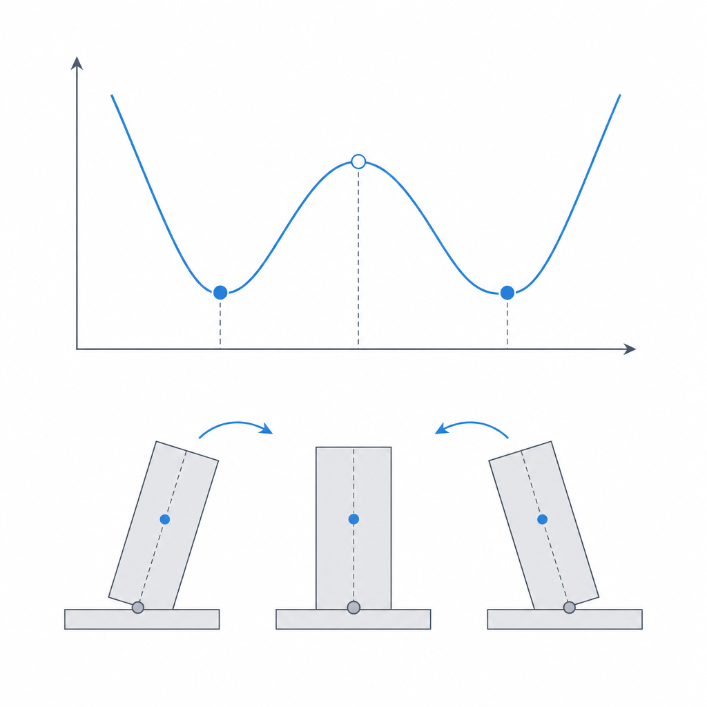
What makes a bistable stable isn't any stop or any friction: it's the shape of its potential energy curve. Picture the mechanism as a ball on a landscape of hills and valleys. There are two valleys — the two stable states — and between them a hill. The ball, released anywhere, rolls downhill to the nearest valley and stays there: that's the physical reason the latch holds with no external energy to sustain it. No actuator is needed, because it sits in a minimum; to get it out of there, you're the one who has to put in the work.
The top of that hill is the tipping threshold: the point where the mechanism's total energy is maximum and, therefore, where the equilibrium is unstable, like the ball perched on top of the hill. A hair to one side and it rolls toward one valley; a hair to the other, toward the opposite one. That threshold sits very close to the geometric dead point — the position where the spring's line of action passes through the pivot and its moment arm about the center of rotation is zero, so the spring produces no torque in either direction — but the two don't coincide exactly except in the idealized case. The net torque that tips the lever isn't supplied by the spring alone: the moment arm of the load you're holding and the geometry of the bars count too. The spring's dead point is the best reference for locating the peak; the real peak is wherever total energy is maximum.
That's why it pays to stop thinking of that peak as "a position" and start seeing it as a boundary. As long as you don't cross it, the spring pushes you back to the state you were in; the moment you do cross it, that same spring switches sides and pushes you toward the other one. Over-center is literally that: carrying the link a little past the dead point, so that in the closed state the spring is no longer at the peak but coming down the opposite slope, pressing against a stop. That sliver of travel past the center is what turns a mechanism that barely holds itself into one that stays put with authority.
The click measures the height of the hill; the firmness, the steepness of the valley
The click isn't an acoustic ornament: it's the signature of the energy being released. Climbing to the peak costs you work — you're loading the spring, carrying the ball uphill. The moment you clear it, all that stored energy discharges at once, driving the lever toward the second valley, and the part falls on its own, accelerating, until it hits. That sharp impact against the stop, fed by the energy the spring gives back, is the click you hear and feel in your fingers.
But it pays to separate two things that are easy to confuse, because two distinct features of the curve govern them. The click energy — how loud it is, how much work it takes to cross — is set by the height of the hill: the higher the peak, the more you have to invest to reach it and the more is released on the way down. The holding firmness — the force it takes to start prying the lever out of the valley — is instead set by the slope of the curve next to the valley, not by the height of the peak. You can have a tall hill with gentle flanks that holds softly and takes a long stroke to cross, or a low hill with a very steep slope right next to the valley that resists the first push hard and tips early. They aren't the same variable.
In practice, the two levers you have at hand — spring preload and travel past center — usually raise both at once, which is why the trick almost always works. But keep it in mind when the behavior doesn't add up: if you want more initial resistance without a more violent click, it's the slope near the valley you have to touch — the geometry of the bars in that stretch — not the total height of the peak.
When crossing the center is what you want
Use an over-center bistable whenever you need a state to hold on its own, with no mechanical catch to engage and no continuous energy to sustain it. The textbook example is the case latch: you swing the lever down, it crosses center, and the lid stays pressed against its gasket with no catch that could pop loose from a brush. The hold-down clamp — the draw latch or toggle clamp — applies the same principle put to work producing force. Near the dead point, the moment arm of the output link tends to zero, so the mechanical advantage shoots up and a modest hand force translates into a very high clamping force.
That multiplication is asymptotic, though, and it pays to understand the fine print. At the exact dead point the mechanical advantage tends to infinity, but the output motion tends to zero: it's a singular point, enormous force and zero travel, where the useful work you deliver is zero. The real clamping happens just before you reach the center, not at it. And in FDM that clamping is capped by the part itself: however much the lever multiplies, the structure yields elastically and the loaded plastic flows, so the "enormous clamping" rarely materializes in full. Once past center, moreover, the load of the clamped part tends to keep the clamp closed rather than open it: pulling on it pushes it against its stop instead of releasing it.
It's also the basis of the tactile switch with a click, and of any control that has to stay "on" or "off" without sitting halfway. The virtue common to all of them is the same: the mechanism has no ambiguous states. It's either on one side or the other, and the tipping threshold makes sure it doesn't end up floating in the middle of the travel.
Design it for FDM, not against it
A printed bistable depends entirely on how you orient the layers. The element that stores the elasticity — whether a flexing arm or an integrated spring — undergoes its maximum deformation right as it crosses center, and that's the classic FDM trap: if the layers stack in the direction the arm bends, the bending tension crosses the layer planes and pulls directly on the bond between beads, which is the weak point. The arm delaminates at the zone of maximum curvature, often within the first few throws. The rule is the one for any flexing part: orient the arm so it bends in a plane parallel to the layers, so the bending tension runs along the beads, in the XY plane, rather than perpendicular to the stack. Lay it down in the plane of the layers whenever the assembly's kinematics allow; the full reason for this anisotropy is in Layer orientation for motion.
The pivot is the other half of the job. It needs a real sliding fit, enough rotational clearance for the lever to swing without binding, because a pivot that rubs eats part of the energy that should go into the click and smears the tipping point. Size it like any printed joint — the gap is designed per side, and counting on the printer to close the hole and grow the shaft, on the order of 0.15–0.25 mm of clearance per side, to be calibrated with a tolerance tower, per Tolerances for moving parts.
And always add a physical stop that limits the travel. It's not optional: with no stop to halt the lever past center, nothing keeps you from pushing further and over-flexing the elastic element beyond its allowable deformation. The stop does two things at once: it precisely defines the closed state (the lever falls to it and stays there) and it protects the spring from being driven to failure. It's against the stop that the click discharges its energy.
Where it breaks: four failures
Four failures stalk a printed over-center, and it pays to name them so you can design them out.
The first is creep in the element that provides the preload. If the spring or arm stays permanently stressed in the closed state, the loaded plastic flows slowly and releases that stress over weeks or months. The precompression you tuned relaxes, the hill drops, and one day the latch that used to tip with authority goes soft or opens on its own. And watch out for a myth here: PLA has a high modulus, but it's among the worst for creep at room temperature, and its Tg is around 55–60 °C, so under sustained load it flows noticeably — more, not less, than a PETG. Instantaneous stiffness is not creep resistance. If the joint is going to spend its life in the closed state, two defenses: at rest, make the preload the minimum that still guarantees the over-center, not the maximum, and reserve for that part a material with better viscoelastic behavior and a higher Tg if it's going to see heat.
The second is delamination of the arm at the point of maximum flex — the one where it crosses center — which is exactly the failure that orienting the layers correctly prevents. If you print it on edge, that's where it splits open.
The third is loss of bistability from excessive pin clearance, already described: too much play in the pivot shifts the dead point and exhausts the over-center until the mechanism stops staying where you leave it.
The fourth is the one the click itself earns the hard way: fatigue from cycling and impact damage against the stop. Every tip is an impact, and a louder click is, by definition, more energy discharged at once against the stop and against the root of the arm. What you celebrated in the tip as firmness — raising the hill for a crisper click — shortens fatigue life: the arm flexes to its maximum on every cycle right where it's weakest, and the stop takes a repeated hammer blow. If the part is going to be cycled thousands of times, don't tune it to the strongest click you can manage: leave it some margin, fillet the root of the arm, and put some meat on the stop.
Tune the stiffness with geometry, not with the material
The stiffness of the elastic element is what sets how much force it takes to cross center and how much energy the click has, and the temptation is to adjust it by switching filament or cranking up the infill. Do it the other way around: tune the stiffness through geometry before material. The bending stiffness of an arm grows with the cube of its depth — the thickness measured in the direction the arm bends, not its width — and falls with the cube of its length, so you have an extremely powerful knob in the arm's cross-section and the moment arm, far more precise and predictable than the one the material gives you. Fatten the arm in the bending plane or shorten it to stiffen the tipping; thin it or lengthen it to soften it. Be careful not to fatten it the wrong way: widening the arm in the direction it doesn't flex raises stiffness only linearly, not as the cube.
The underlying reason not to trust it to the material is that in FDM the part's effective modulus isn't the filament's: it depends on the infill, the perimeter count, the orientation, and the quality of the weld between layers, and it varies a lot from one part to the next. An arm calculated on PLA's nominal modulus can come out considerably softer if it's hollow inside. So however much you refine the geometry on paper, validate with a prototype: print the real bistable, throw it, measure whether the click is the one you wanted and whether the latch holds, and correct the arm's depth if you have to. Geometry gives you the control; the prototype gives you the number.
If what you have on your hands is more of a flexing hook for catching than a lever that tips, the boundary between the two is thin, and the holding reasoning is in Snap-fits that won't release: the same question — how much firmness, how much it lets itself be opened — solved with different geometry.