Acme and ball screws: rotation to linear, with force
A screw is the most direct—and most controllable—way to turn rotation into straight thrust. A small motor spins a threaded rod; the nut, trapped on it, can't spin along with it, so it has no choice but to travel along the axis. What's interesting isn't the mechanism itself—it's a thread, something you've understood since the first time you tightened a bolt—but the enormous mechanical advantage it gives you: one full turn of the screw moves the nut just a few millimeters, and in exchange for that short displacement you get an axial force that multiplies the input torque many times over. That's why a screw drives tables, presses, and Z axes where a belt would slip. And that's why, when you print one in FDM, the difficulty stops being the kinematics—which are simple—and shifts to the material: a plastic thread has to withstand exactly the load the screw is busy amplifying.
Lead sets the motion; friction decides whether it backs off
All of a screw's kinematics fit into one number: the lead, how far the nut travels for each full turn of the screw. If the lead is 2 mm, one turn is 2 mm of travel, half a turn is 1 mm, and the resolution of your positioning is that lead divided by the angular resolution of the motor: with 200 steps per turn and a 2 mm lead, each step is 2/200 = 0.01 mm of linear displacement. Don't confuse lead with pitch: on a single-start thread they're the same, but on a multi-start thread the lead is the pitch multiplied by the number of starts, and raising the number of starts is the way to gain speed without cutting the pitch so fine that the thread becomes hard to print.
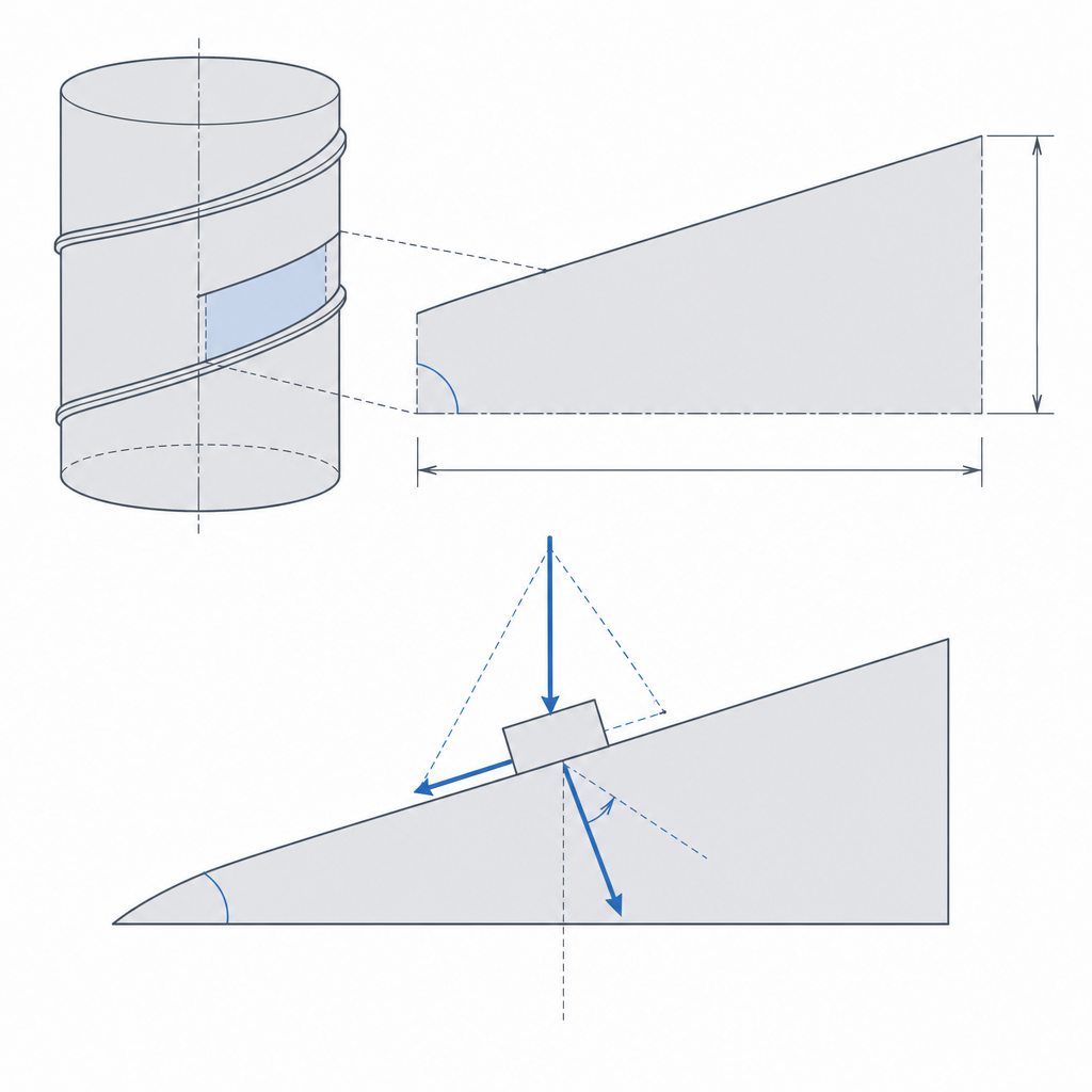
What really governs the behavior under load isn't the lead alone, but its relationship to friction. Mentally unwrap one turn of the thread: it's an inclined plane wound around a cylinder, and its slope is the helix angle. When you push the nut axially, that force resolves on the inclined flank into a component that tends to spin the screw—like a weight sliding down a ramp—and a normal component that presses the flanks together and generates friction. If the helix angle is small compared to the friction angle of the material pair, the component pushing the screw to turn never overcomes the friction holding it back: the load can't drive the screw backward, and the thread is self-locking. Raise the lead and the helix angle grows; overshoot and the thread becomes reversible, backing off on its own the moment you load the nut and release the motor.
There's a subtlety that works in your favor with the Acme: the 29° trapezoidal flank doesn't press perpendicular to the axis but against a wedge, so the effective friction is higher than on a square thread of the same pitch. That widens the self-locking margin. The real boundary, moreover, isn't the exact crossing of the friction angle: for a load not to back off reliably—accounting for vibration and margins—you want to stay comfortably below it, not skirting the limit. Hence the practical rule: small lead and high friction give a thread that holds the load with the motor stopped. A fine-pitch Acme, precisely for this reason, keeps the table still without the motor spending torque to hold it. You pay the price in efficiency, because that same friction that gives you self-locking eats a good part of the input torque as heat.
Acme versus ball screw: slide or roll
The Acme thread is trapezoidal: the flank isn't sharp like a metric bolt's but an open wedge of about 29°, robust and easy to machine—and, what matters here, to print. The nut slides on those flanks, plastic on plastic or plastic on metal, and that sliding is pure friction: a typical Acme runs at 30–50% efficiency, and a printed, self-locking Acme lives at the low end of that range, more like 20 to 40%. That's no accident: self-locking is thermodynamically the same as sub-50% efficiency, so the better it holds the load, the less efficient it is. It's the thread for someone who wants force and held position, not speed or efficiency.
The ball screw eliminates the sliding by replacing it with rolling: a row of steel balls circulates between screw and nut, recirculating through a return channel, so the contact stops being flank against flank and becomes ball rolling on track. Rolling barely rubs, so efficiency tops 90% and backlash can be driven practically to zero with preload—though that same preload that removes the play also cuts efficiency and life; it isn't free. The catch you already know: without friction there's no self-locking, a ball screw backs off on its own the moment you release the motor, and it needs a brake or an energized motor to hold a load. And there's a bigger drawback for us: a ball screw lives on micron tolerances, hardened tracks, and calibrated balls. FDM can't replicate that. You can print something shaped like a ball screw, but the balls won't roll clean over a profile with layer steps, and what you'll have is a poor, expensive Acme. The ball screw, on a printed part, is metal hardware you embed, not geometry you slice (covered in Embedded hardware: magnets, bearings, and inserts).
| Criterion | Acme thread (trapezoidal) | Ball screw |
|---|---|---|
| Contact | Sliding flanks | Recirculating balls rolling |
| Efficiency | ~20–40% self-locking, up to ~50% without self-locking | >90% |
| Self-locking | Yes, at the low efficiency end | No: backs off on its own |
| Axial play | Moderate, grows with wear | Near zero with preload |
| In FDM | Directly printable | Only as embedded metal hardware |
For printing, in the vast majority of cases the answer is Acme: it holds without power, tolerates the process variability, and doesn't depend on components you can't make. Save the ball screw for when speed and efficiency are paramount and you're willing to fit a genuine bought-in assembly.
Print the screw upright and the nut in a material that holds
The screw's orientation leaves no doubt: vertical, with the axis perpendicular to the bed. That way the thread is built in layers perpendicular to the axis, each one adding a ring of the helix with its full trapezoidal section supported, with no overhangs that would demand supports impossible to remove from between the threads. Lying down, the screw fills with supports embedded in the thread, with the profile flattened on one side; upright, the helix builds clean. That same orientation is what decides the strength of the assembly, because it puts the flanks to work along the beads and not between layers (the full reasoning is in Layer orientation for motion).
A caveat is in order: even upright, the lower flank of each thread is an overhang whose angle from horizontal is the helix angle itself. With small leads the helix is gentle and that overhang comes out self-supporting; with large leads or multi-start threads the lower flank can exceed your printer's overhang limit and sag. One more reason to keep the lead short on a printed thread.
The critical part, however, isn't the screw: it's the nut. That's where the axial load the screw amplifies is shared across a few plastic threads, and that's where the mechanism breaks. Three decisions save it or doom it. First, the material: a PLA nut under sustained load has its days numbered—PLA is stiff but brittle, it flows slowly under maintained load (creep, made worse by heat), and its crests fail brittle; PETG and especially nylon are tough and wear-resistant, and they withstand sliding what PLA tears off. Better still, embed a real metal nut (a brass Acme nut) and let the plastic merely hold it: you move the flank problem to metal, where the material works well. Second, the length: the more engaged threads, the more flanks you spread the load over and the less pressure each one bears. A nut of a couple of threads concentrates everything on two crests that get torn off; a long nut, of many threads, spreads it and lasts. Third, the flank clearance, which you size exactly like any other printed fit: just enough for the nut to thread on and turn without binding, knowing that a printed thread comes out tight and that zero on screen is interference in the part. The detail of printed threads and inserts is developed in Threads, inserts, and nuts.
Backlash ruins bidirectional positioning
Between the screw's flanks and the nut's there's always some gap—on a printed thread, quite a lot. As long as you push the nut in a single direction, that gap goes unnoticed: the flanks are seated and the nut follows the screw faithfully. The problem shows up when you reverse rotation. Before the nut starts moving the other way, the screw has to spin free just enough for its flanks to cross the gap and seat again on the opposite face. During that spin the nut doesn't move: it's a dead zone, a stretch where you command displacement and get none. That's backlash, and it ruins any positioning that demands precision in both directions—an axis that moves up and down to a setpoint, a table that goes and returns.
If you only push in one direction and always return approaching from the same direction, you can live with backlash by ignoring it. If you need precision in both directions, you have to eliminate it, and the classic solution is an anti-backlash nut: two half-nuts mounted on the same screw and spring-preloaded to push them apart axially, so one seats its flanks against one face of the thread and the other against the opposite. Between the two they leave no gap in either direction; the spring takes up the clearance and keeps it taken as the flanks wear. Watch its limit: this scheme only compensates axial backlash, and the spring force sets the maximum useful load. If the working axial load exceeds the spring's preload, one of the halves lifts off and the play returns; size the spring so its preload exceeds the load you're going to move. The price is more friction and a bit more drag torque, but it's what turns a printed screw into something you can actually position with.
Threads strip, plastic binds, play grows
It's worth naming the failure modes, because each is prevented differently. The first and most common is thread stripping of the nut: under axial load, the few plastic flanks carrying the thrust deform, give way, and end up swept clean like a stripped thread. PLA is the material that withstands it worst—brittle and prone to creep; the remedy is a long nut, a tough material, and, if the load is serious, an embedded metal flank. An early symptom is the assembly losing force and starting to slip axially: you're already tearing off the crests.
The second is binding, and it's the opposite of the first: insufficient flank clearance, or a screw that expands with service heat or with friction itself, until the nut can no longer slide and seizes. It shows as hard spots along the travel or a drag torque that climbs until it stalls the motor. You prevent it with the right clearance—measured on your printer, not copied from a table—and by leaving margin for expansion if the screw will heat up.
The third is slow and treacherous: growing backlash. A nut that started snug wears its flanks against the screw every time it moves, and that wear widens the gap. A mechanism that positioned finely fresh off the printer develops a dead zone over the cycles, and you lose it without anything breaking all at once. The spring anti-backlash nut is precisely what compensates this: the spring takes up the clearance as it appears, so the play doesn't grow even though the flanks do wear.
With the screw sized and the nut sorted, the next step is usually joining it to the motor and the structure without the joint itself introducing its own play: that's where the threads holding it all together come in, and the hardware you embed so metal carries what plastic can't. Start with Threads, inserts, and nuts.