Roller chain and sprocket: high torque over distance
When a belt would slip under the torque you need, or stretch until it loses sync, there's another path: mesh geometry against geometry. It is the brute force of a tooth pushing on a roller. A roller chain doesn't transmit torque by friction like a smooth belt, nor by the elastic grip of rubber teeth like a timing belt: it transmits torque because each roller physically drops into the valley between two sprocket teeth and pushes. There's nothing to slip. The transmission ratio doesn't depend on tension or on a friction coefficient, but on a whole number of teeth, and that makes it exact and brutally robust. You pay for it elsewhere: in noise, in angular backlash, and, if you print the sprocket, in the hub-to-shaft joint, which is where all that well-transmitted torque concentrates and breaks the part.
Why the ratio is exact, and why it pulls unevenly
A chain's kinematics is governed by tooth count, not by rolling contact. Each chain roller seats in the gap between two teeth, and the sprocket advances one tooth for every link that wraps onto it. If the driving sprocket has 15 teeth and the driven one 45, the ratio is exactly 3
, without the accumulated drift a smooth belt would have from microslip. That exactness is the whole point of a chain: it positions by counting, not by gripping.But there's an effect you can't ignore, and it's pure geometry: the polygonal effect (or chordal action). A chain doesn't wrap over a circle, but over a polygon whose vertices are the rollers seated on the teeth. As the sprocket turns, the point where the chain touches the sprocket rises and falls between the radius to the polygon vertex—the roller, at the maximum pitch radius—and the radius to the midpoint of the side—the apothem, the minimum radius. The result is that, for a constant angular velocity of the sprocket, the linear velocity of the chain oscillates with each tooth pitch. That oscillation shows up as vibration and as a variation in output speed that grows more pronounced the fewer teeth the sprocket has, because the polygon is coarser: an 8-tooth sprocket is an octagon you feel at every tooth, while a 25-tooth one is already close to a circle.
When it's the right tool and when it isn't
The chain shines exactly where the belt is weak. It transmits high torque without slipping, tolerates large center distances without tensioning the drive so hard that it overloads the bearings, and survives dirty or hot environments where a timing belt would skip a tooth or degrade. If you need to move a lot of torque between two separated parallel shafts, it's hard to beat.
Where you shouldn't choose it is the flip side of its virtues. It's noisy: each roller impacts its tooth as it engages, and that cadence of impacts is noise you cannot eliminate. And it has backlash between links: every pin-bushing joint has its play, and the sum of all that play along the run ruins any attempt at fine positioning. For a shaft that has to run quiet and position to within a degree, choose a timing belt or a gear, not a chain. The chain is for torque and robustness, not for finesse.
Printing the sprocket: the tooth, the orientation, and the hub
The first thing to understand is that a sprocket's tooth profile is not arbitrary: it has to match the pitch of the real chain you're going to fit. The pitch is the distance between the centers of consecutive rollers, and together with the roller diameter it defines the geometry of the valley where that roller must seat. A sprocket whose profile doesn't correspond to the pitch of its chain will mesh badly, will load the tooth tip instead of the valley, and will wear out fast. Always start from the dimensions of the real chain you're going to fit, not from a generic drawing.
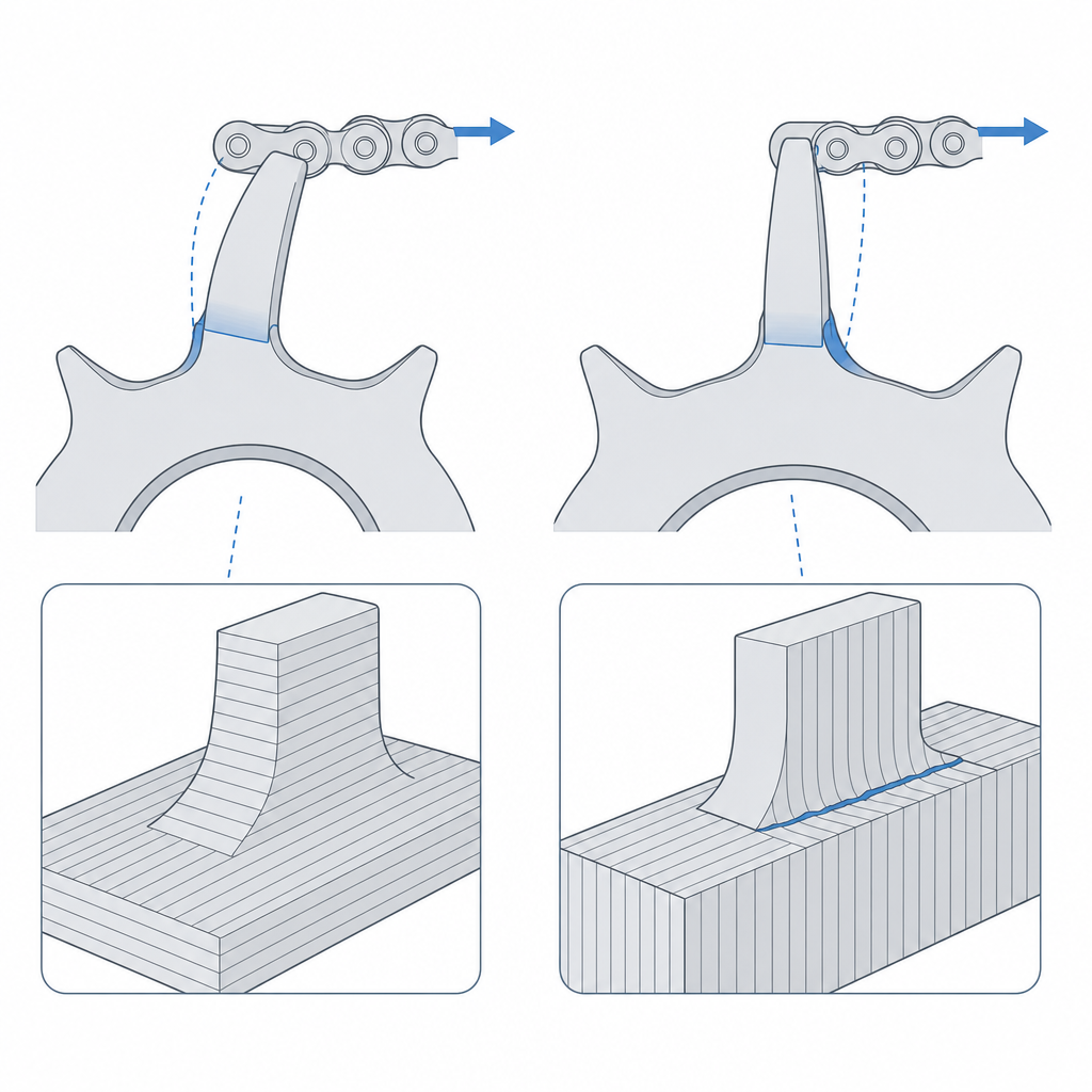
The sprocket's print orientation decides whether the tooth survives. When the roller pushes on the flank, the tooth works as a cantilever beam: the load that breaks it is bending at the root, with tension on the loaded side of the base. In an FDM part the weak plane is the bond between layers, which opens under tension. If you print the sprocket lying flat, with the tooth face in the XY plane and the layers stacked along the axis, that bending stays contained within the layer plane and doesn't pull the layers apart in tension, and the tooth holds. Printing the sprocket on edge makes the tooth root coincide with a seam between layers, exactly where bending tension delaminates it on the first hard load. I work through the reasoning for this rule in Layer orientation for motion.
And then there's the hub, which is where the part is really decided. The chain's whole virtue—transmitting high torque without slipping—turns into a concentration of torque right at the joint between the sprocket and its shaft, and a printed hub-to-shaft joint is among the most fragile things FDM produces under torque. A set screw clamping against a smooth shaft crushes the plastic and slips; a thin hub cracks along the perimeter seam when you tighten it. Oversize it: a generous wall around the shaft, and solve the torque transmission with a threaded insert for the set screw or, better, with a non-circular shaft profile—a milled flat, a hexagon—that blocks rotation by shape and not by friction. How to embed a threaded insert properly is in Embedded hardware: magnets, bearings, and inserts.
| Decision | Starting value | Why |
|---|---|---|
| Tooth count | ≥ 17 at speed; fewer is fine at low speed | tames the polygonal effect and noise |
| Tooth profile | to the pitch of the real chain | the roller seats in the valley, not on the tip |
| Orientation | tooth face in XY | bending stays in the layer plane and doesn't delaminate |
| Hub | thick wall + insert or shaft with flat/hexagon | otherwise torque breaks the hub-to-shaft joint |
| Material | nylon (dry) or PETG | they resist roller wear better than PLA |
Assembly: coplanar shafts and a correctly tensioned run
A perfect sprocket is worth nothing if you mount it misaligned. The two sprockets must end up coplanar and with their axes parallel: if one sits ahead of the other, or their axes aren't parallel, the chain enters at an angle under load, rubs the side flanks of the teeth, and eventually climbs off or wears diagonally. On a printed drive this is easier than it sounds, because the shaft supports are usually FDM parts that flex under load: check coplanarity with the chain fitted and reinforce the supports until they no longer flex.
And although the chain tolerates separated centers without tensioning to the limit, tension still matters. It needs a slack run with some sag—neither sagging loose nor stretched bar-tight—because a run that's too slack whips, rides up onto the tooth tips, and skips just like a worn chain. On long runs, or when you can't adjust the center distance, add a tensioner or shoe that bears on the slack run and takes up the sag. The right tension isn't the maximum: it's the minimum that keeps the run under control.
One-piece printed chain: viable, but for light loads
It's tempting to print the whole chain of captive links print-in-place, in a single part, with the pins already movable and nothing to assemble afterward. It's viable, and as a demonstration of what a printer can do it's eye-catching. The key is the pin clearance: each joint needs on the order of 0.15–0.25 mm per side so the link doesn't fuse to its neighbor and the chain actually flexes the moment you peel it off the bed. It's the usual clearance for any print-in-place part; the reasoning for thinking about play per side rather than per diameter is in Tolerances for moving parts.
But the reality is different: a chain like this carries very little load. Each printed pin is a thin plastic cylinder working in shear and bending, with a play that—however finely you tune it—spreads the load worse than a metal bushing, and joints that wear fast. It works for a toy mechanism, a kinematic demonstration, or a drive that carries almost no load. For real torque, the division of labor is clear: a commercial metal chain for the links, and print only the sprocket, which is the part truly worth making custom. Don't ask a printed chain to do the work of a steel one; it can't.
The three failure modes that end a chain drive
A chain drive fails in three ways, and it's worth recognizing them because each one warns you before it fails outright.
The first is tooth pointing. With use, especially if the material is soft or the mesh is poor, the teeth sharpen: they lose material on the flank and thin toward the tip. A pointed tooth no longer retains the roller well in its valley, and the chain starts to climb up the tooth flank until, under peak load, it skips a whole tooth. That skip is noisy, abrupt, and usually comes with a loss of sync. It's the main reason the material matters: a brittle PLA sprocket wears and chips long before a nylon or PETG one, which take the roller's wear considerably better.
The second is chain elongation. A chain doesn't "stretch" elastically; it elongates because the wear at each joint keeps removing material from the pin and the inside of the bushing, and the effective pitch grows link by link along the whole run—the outer roller spins free and does not set the pitch. An elongated chain no longer seats its rollers at the bottom of the valleys, but rides higher and higher, toward the outer diameter of the sprocket, until it ends up riding on the tips and skips. It's the same outcome as tooth pointing, reached from the other half of the mesh: either the tooth wears, or the chain elongates, and in both cases the roller ends up where it shouldn't.
The third, and the one specific to printing, is hub failure under torque. We've said it already, but it's the one that destroys the most parts: the torque the chain transmits so well goes to concentrate at the hub-to-shaft joint, and if that joint is a set screw against a smooth shaft or a thin-walled hub, it slips, crushes, or cracks. It isn't a failure of the chain or of the mesh: it's the printed part giving way exactly where it takes all the load. If your chain drive fails and the teeth are healthy, start with the hub.
With the mesh solved and the material chosen, the bottleneck of any printed sprocket almost always shifts to how you fix it to the shaft: so that torque doesn't tear off the hub, size that joint by the same rule as any other press fit and embed the insert properly, as detailed in Embedded hardware: magnets, bearings, and inserts.