Capstan cable drive: smooth, backlash-free reduction
A cable wrapped a few turns around a drum can hold many times more tension than what you apply at the other end, with no knots, no clamps, and without the cable slipping. It's the same effect that keeps a boat moored while one sailor holds the loose end. And it's the basis of the capstan cable drive: a small drum pulls a large pulley through a wound cable, and out of that comes a reduction with extremely fine resolution, no backlash, and almost no noise. That's why it gets chosen for precise robotic arms, telescope mounts, and gripper fingers that have to move smoothly and without jerks. There are no teeth meshing and no play to take up: just a well-guided, well-tensioned cable. And like almost everything in FDM, it works or fails on a few tenths of a millimeter of geometry — here, the geometry of the groove that guides the cable.
Why a few turns hold so much tension
The physics of the capstan is one of the few you can write in a single line and understand completely: the tension the cable can hold grows exponentially with the angle it wraps around the drum. The formula is Euler-Eytelwein's, T_tight = T_slack · e^(μθ), where μ is the friction coefficient between cable and drum and θ is the total wrap angle, measured in radians. What matters isn't the formula but what it says: every turn you add contributes 2π radians to θ, and because θ is in the exponent, the holding capacity doesn't add up — it multiplies.
Let's look at it with numbers. With a modest friction coefficient, μ = 0.3, a single full turn (θ = 2π) gives you a factor of e^(0.3·6.28) ≈ 6.6: the tight side holds nearly seven times the tension of the slack side without the cable moving. Three turns (θ = 6π) take it to e^(0.3·18.8) ≈ 290. The progression is brutal precisely because it's exponential: that's why a capstan needs no external radial force pressing the cable against the drum — no pinch roller, no clamp; just enough turns. The normal force that creates the friction is supplied by the cable itself as it curves under tension over the drum.
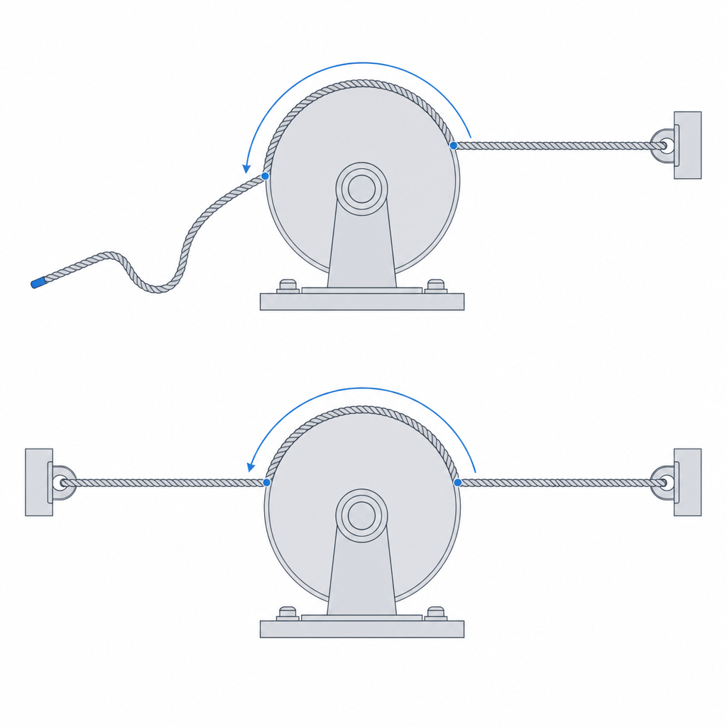
Now, that Euler-Eytelwein effect is not what transmits torque in a robotics capstan, and it's worth being clear about this from the start so you don't size it with the wrong formula. Distinguish two machines that share a name. The friction capstan — the sailor's — has a free end: the cable wraps around the drum and is held by friction alone, and there Euler-Eytelwein rules. The capstan drive, the one that moves an arm or a mount, has the cable anchored at both ends: torque passes through direct tension in the cable, not through grip. In that case the turns aren't there to hold the output tension, but to spread the load along the drum, maintain contact during winding, and keep the entire effort from falling on the anchor point. The rest of this article is about the second one, because that's the one you care about for moving something with precision.
The actual reduction, and where its ceiling is
The reduction of a capstan drive comes from the winding geometry, not from setting two cylinders tangent like a belt. The cable winds onto the small-radius driving drum and is anchored to a large-radius output sector; when the drum turns, it takes up or pays out cable and drags the sector along. The speed ratio, and the torque ratio, is that of the two radii: i = R_output / R_drum. It's like a pair of gears, but with no teeth and no reversal backlash.
That doesn't make it an unlimited reduction. A single capstan stage gives practical ratios of ~5 to ~20, limited by two things: how many turns of cable fit along the drum without the winding getting disorderly, and how far you can narrow the drum before the cable, curving in a small radius, suffers and bending friction shoots up. For larger ratios you chain stages, just as in a gear train. If you were expecting a huge reduction in a single pass, adjust the expectation: what the capstan gives you over a gear isn't ratio, it's smoothness and the absence of backlash.
And there's a first-order limitation that's easy to forget: the travel is finite. The drum can only turn as many times as it has cable wound before running out on one side, so the output angular range is bounded by the cable length and the drum radius. A capstan doesn't give continuous rotation. For a gripper finger or a camera axis that travel a few degrees that's plenty, but if what you're after is continuous tracking — a mount that follows a star with no stop — you have to design the travel with margin or accept that rewinding will be needed.
When it's the right drive and when it isn't
The capstan shines in a very specific niche: when what you want is precision and smoothness, not brute force. Zero backlash, very low inertia — a cable weighs almost nothing compared with a gear train — and quiet operation because there are no tooth-against-tooth impacts. For a camera that has to aim without jumps, a telescope mount that follows a star, or the finger of a robotic gripper that closes with a delicate touch, it's hard to beat. With the cable anchored at both ends, every motor step is a real step at the output, with no intermediate backlash, and that's exactly what a fine positioning system needs.
What it isn't is a power transmission. As long as the cable is well anchored, it doesn't slip under normal load — it pulls through direct tension — but the assembly has its limit elsewhere: if the load exceeds what the cable or the anchor can take, the cable stretches too much, the anchor gives way, or, in a poorly wound drum, the turns start sliding over the drum before the anchor takes over. There's no catastrophic failure, but there's also no way to pass high continuous torque through a thin cable. To drag heavy loads or hold high torque in a sustained way, the right choice is a gear or a toothed belt, not a capstan. Know the limit of your cable and your anchors, and design to stay comfortably below it.
The drum: a helix that guides each turn
This is where FDM comes into play, and where the capstan stakes its performance. If you wind the cable onto a smooth cylindrical drum, the turns have nowhere to settle: under tension, a turn slides sideways and rides up over the one next to it. When two runs of cable cross and pile up, the winding gets disorderly, the load stops spreading evenly, and in the worst case the cable jams and blocks the motion. It's the main failure mode of a badly designed capstan.
The solution is to model the drum with a helical groove, a thread with a pitch equal to the cable diameter, that takes each turn into its own channel and keeps it separated from the next. The helix fixes where each run will seat, keeps them from riding up over one another, and spreads the winding cleanly along the drum. The helix pitch should be slightly larger than the cable thickness so it enters without forcing but without enough play to let it jump channel. Account, too, for the fact that a braided cable flattens and widens under tension: leave margin for that widening and don't sit right at the limit. It's the same per-side margin reasoning that governs any printed fit and that you have worked out in Tolerances for moving parts.
Print the drum with its axis vertical on the bed. That way the helical groove is generated as a horizontal contour that rotates layer by layer, and the channel walls come out well defined. Account for one nuance: the "roof" of each channel — the upper wall of the thread — is an overhang whose angle depends on the pitch. With small pitches that overhang comes out very shallow and prints with no trouble; with thick cables and large pitches it can sag and call for a tweak in orientation or geometry. Laying the drum down is worse for another reason: the circular section forces you to support the lower half and the groove comes out irregular right where it has to guide the cable. This orientation also has the other side that Layer orientation for motion covers: it decides which way the drum's weak planes point, and a drum loaded in torsion by the cable prefers layers perpendicular to its axis.
Decide already in the model how you're going to anchor both ends of the cable. In a capstan drive this isn't an assembly detail: it's what transmits the torque. Each cable end has to be fixed to the drum and to the output sector, because the pull passes through the anchored cable, not through the friction of the winding. The usual approach is a knot housed in a blind cavity — an internal widening where the knot gets trapped and can't come out through the pass-through hole — or a small set screw that pinches the cable against the part. Model that cavity or that screw seat in the same step in which you draw the helix; solving it afterward, with the drum already printed, almost always forces a reprint.
| Parameter | Starting value | Why |
|---|---|---|
| Helix pitch | Ø cable + 0.15–0.3 mm | one turn per channel, without riding up or sitting loose; leaves margin for the cable widening under tension |
| Channel width | Ø cable + per-side clearance | the cable seats without forcing; see Tolerances for moving parts |
| Channel bottom | rounded, r ≥ Ø cable / 2 | a sharp edge cuts the cable by bending (steel) or by abrasion (Dyneema) |
| Wrap turns | 2–4 | spread the load and unload the anchor during winding |
| End anchoring | knot cavity or set screw | with no anchor there's no torque: the cable would only grip, not pull |
Pretension both runs or a dead zone will appear
A capstan moves the load in both directions by pulling, alternately, on one run or the other of the cable. The problem appears in the run that, at any given moment, is not pulling: if it goes slack, the system has play again — a dead zone in which the drum turns a little before the return run tensions and the output starts to move. And then you've lost exactly what you went to the capstan for, the absence of backlash.
The cure is pretensioning. The cable is mounted with a deliberate initial tension so that both runs are always taut, even when neither is working under load. That way, when the drum reverses direction, the run taking over was already tensioned and the output responds immediately, with no dead gap. You achieve it with a spring in series with one of the ends — which absorbs the cable's stretch and the small length variations while keeping the tension — or with a tensioning screw that draws an anchor in and tightens the cable to just the right point. The spring is more forgiving: braided cable yields a bit with use and detensions slowly, and a spring recovers that loss on its own, whereas a screw forces you to retighten now and then.
Don't overdo the pretension. An excessive initial tension doesn't buy more useful stiffness: it just permanently loads the cable, the drum, and the bearings, accelerates wear of the track, and, in a printed part, introduces a sustained load that the plastic will slowly relax over time — and that relaxation steals your pretension right where you need it stable. Tension just enough that the slack run never goes fully slack in the worst-case load, and leave it there.
The failure modes and the material that holds them off
A printed capstan fails in several ways, and it's worth recognizing them separately because each one calls for a different fix.
The first is the cable riding up and jamming. Almost always it's a lack of guiding: a missing helical groove, one with the wrong pitch, or one printed so coarsely it doesn't contain the turns. The turn leaves its channel, climbs over the adjacent one, the runs pile up, and the motion locks. It's cured in the drum geometry, with a helix of correct pitch and clean channel walls — hence the insistence on printing the drum axis-vertical.
The second is winding slip. Careful: this isn't the same as the slipping of a friction capstan: with the cable anchored at both ends, the assembly doesn't stop transmitting torque under normal load. Slip appears when the turns are too few to unload the anchor during winding, or when the track has glazed — with use, the rubbing polishes the groove surface and lowers the friction between cable and drum right where you need it for the turns to grip while the anchor takes over. The first cause is fixed by adding more turns. The second has no fix in place: you can't sand the bottom of an already-assembled millimeter-pitch thread, so you have to reprint the part or redesign to a material that holds its texture better.
The third is wear or cutting of the cable. A sharp edge at the rim of the printed groove acts like a blade, and the cable works against it on every cycle. In steel cable the dominant failure is bending fatigue: the wire flexes millions of times over the same point and one strand gives, then another, until it fails. In Dyneema or UHMWPE — the de facto standard in fine robotics, because it barely fatigues when flexing — the dominant one is abrasion: the edge saws through the fibers. In both cases the remedy is the same. FDM's layer-by-layer deposition tends to leave stepped, sharp edges, so round the edges and the bottom of the groove: a radius at the bottom of the channel greater than or equal to the cable radius spreads the contact pressure and removes the edge. It's the same principle that keeps a sharp corner from concentrating stress in any loaded part, applied here to an element that passes millions of cycles rubbing.
Deciding the helix pitch, the channel clearance, and the anchor fit is, in the end, the same calibration work as any other printed joint: it comes from measuring your machine, not from copying a table. Tolerances for moving parts takes you from function to gap, and that number — the real gap of your nozzle and your material — is what makes the cable seat in its channel without forcing and without jumping.