Eccentric drive: reciprocation from an offset center
An eccentric is the cleanest way to build a crank when the radius you need is too small for a throw. Instead of carving a thin, delicate arm out of a crankshaft, you mount a whole disc on a shaft that doesn't pass through its center: the axis of rotation sits offset from the geometric center by a distance we call the eccentricity, or offset, e. As the shaft turns, the disc's contour sweeps an orbit, and any collar wrapped around it is forced to move back and forth. You've turned continuous rotation into reciprocation without a single fragile throw: the journal is the entire solid disc. Where a crank with a 2 mm radius would be a wire that bends, an eccentric with 2 mm of eccentricity is a 30 mm disc that carries the load without flexing.
Kinematics: a crank-slider in disguise
The kinematics hold no surprises: an eccentric is a crank-slider mechanism, just disguised. The eccentricity e plays exactly the role of the crank radius. The center of the disc traces the same orbit a crank journal of radius e would trace, and the collar — the ring wrapping the disc, the eccentric strap — picks up that motion and passes it to the connecting rod. That's why the reciprocating stroke is 2e, twice the eccentricity. The disc pushes the ring e one way through half a turn and e the other way through the other half; the travel between the farthest and nearest points is two eccentricities.
The motion is very nearly sinusoidal. If you project the circular orbit of the disc center onto the direction of reciprocation, what you get is a cosine: the ring accelerates from rest at the ends of the stroke, reaches peak speed passing through the center, and brakes again. It's not a perfect sinusoid — the finite length of the connecting rod introduces the same asymmetry as in any crank-slider, more pronounced the shorter the rod is relative to the eccentricity — but for eccentricities small compared with the rod length the sinusoidal approximation is good enough to predict speeds and accelerations. The output isn't strictly linear reciprocation unless a slider or the rod itself guides the ring: the point on the ring actually traces a small orbit, just as in any crank-slider.
The structural advantage is the whole point of the mechanism. In a conventional crank, the journal is a thin cantilevered pin and the crank radius is the distance from that pin to the axis; reducing the radius means moving the pin toward the axis until there's no solid material left around it. In an eccentric the "journal" is the entire disc, so the eccentricity can be as small as you like — tenths of a millimeter if needed — without compromising the section that passes the torque through. Crank radii that would be impossible with a throw are trivial to get with an off-center disc.
When to choose an eccentric over a crank
The eccentric wins when three conditions come together: short stroke, continuous through shaft, and high torque. Short stroke because the amplitude is 2e and the eccentricity is limited by the disc radius itself; asking it for a long stroke forces a huge disc. The through shaft because, unlike a crankshaft that has to be broken up into throws, an eccentric leaves the shaft straight and whole running through it: you can stack several in series on the same shaft, phased apart, and draw several coordinated reciprocations from a single rotation. And high torque because that's where the ruggedness pays off.
Its natural home is displacement pumps, small presses, vibratory screens and sieves, feeders: anywhere you want to push hard over a short travel many times per second. Against a thin crank, the eccentric gives you an enormous bearing surface — the whole disc contour against the whole ring interior — instead of concentrating the load on a pin. That distributed surface is what makes it stiff and what lets it swallow torque without anything bending. The trade-off is friction: that same generous contact rubs along its full extent, and that friction is what you'll have to manage when you print it.
The radius sets the limit on eccentricity
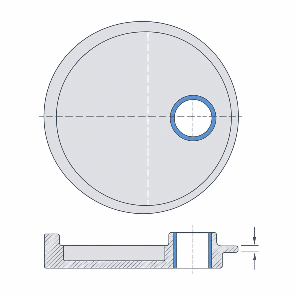
Eccentricity has a geometric ceiling worth sizing before you draw anything. The center of the shaft hole moves away from the disc center by a distance e, so on the thin side of the disc the wall left between the hole and the edge measures R − e, where R is the disc radius. The larger the eccentricity relative to the radius, the thinner that wall gets. Overdo it and the thin side becomes fragile — it's the area that carries the most torque and the first to give.
As a starting rule, leave on that thin side at least three or four continuous perimeters of wall — on the order of 1.5 mm with a 0.4 mm nozzle — beyond the shaft hole itself. That fixes a practical ceiling on the eccentricity well below R, and it tells you when an ambitious offset forces you to enlarge the disc rather than thin the wall. The 2e stroke you're after comes out of that calculation, not from a number picked in isolation.
Print it flat, and mind the shaft concentricity
In FDM there's only one good orientation for the sliding fit: the disc with its face in the XY plane, lying flat on the bed, with the ring wrapping it. That way the sliding between disc and ring happens in the plane of the layers, not across them, and the two contact surfaces come out as cylindrical as your machine can manage. A disc printed on edge would come out with its orbit ovalized by the overhang and with the layer lines exactly where they rub the most — the worst possible place. The full reasoning for why orientation rules any moving part is in Layer orientation for motion.
That orientation carries a trade-off that bites as soon as the torque rises. Lying it flat in XY stacks the layers perpendicular to the circumferential tension the torque induces in the ring, exactly FDM's weak direction. In other words, the orientation that gives you the best roundness for sliding is also the one that leaves the ring most exposed to splitting open under radial load. We deal with it below, in the failure modes; for now, hold onto the idea that "flat" optimizes the fit, not the ring's strength.
The number that really decides whether the eccentric works is the actual concentricity of the printed shaft relative to the disc. The design eccentricity is the distance between the center of the shaft hole and the geometric center of the disc, and that's the dimension that produces the reciprocation. If the hole comes out off-center on its own — from shaft slop, from a hole that didn't come out round, from first-layer squish narrowing the opening — the actual eccentricity is no longer the one you drew, and the amplitude goes with it. Here the printed hole runs into the usual problem: it comes out narrower than nominal and, if the shaft has slop inside, the effective eccentricity stops being a fixed value and becomes a range. Size that hole like any precision fit — the full reasoning is in Tolerances for moving parts — and, if the eccentric is going to turn a lot, consider housing a bearing or a bushing instead of spinning plastic against the bare shaft, as detailed in Embedded hardware: magnets, bearings, and inserts.
The clearance between disc and ring is reasoned per side, like any slider, and it has to be uniform around the entire contour: the ring sweeps the whole disc contour over one turn, so any tight zone shows up as a hard spot once per revolution. A smooth contact surface — or a bushing of a lower-friction material — reduces wear on the ring, which is the first point to wear out.
The reciprocation is only complete if the ring captures the disc
It's worth being clear about a difference that sets the eccentric apart from a cam. A cam pushes its follower through one half of the turn and relies on a spring or on gravity for the return in the other half: the contact is one-sided. The eccentric can do the same — push and let something bring it back — but its real strength is that the ring almost always captures the disc completely. Control in both directions doesn't come from the disc dragging the ring; it comes from geometric capture. The ring is circular and surrounds a circular disc of the same diameter plus clearance; the center of the disc shifts, but the contour always fills the ring, which stays captive with nowhere to go. So the reciprocation is governed both on the advance and on the return with no need for a return spring.
All the clearance of that sliding pair shows up at the ends of the stroke, where the ring reverses direction: that's where the gap between disc and ring registers as a knock. It's the same clearance you measure per side, which is why a well-fitted eccentric is silent and a loose one taps once per revolution. If you open the ring or replace it with a follower that merely rests against the disc, you're back in cam territory: half a turn of push and half a turn at the mercy of whatever returns the follower, with the risk that it drops away at high speed.
Balancing and failure modes
The disc's mass is, by definition, off-center. That means the eccentric is an imbalance by construction: its center of mass doesn't coincide with the axis of rotation, so every revolution flings out a centrifugal force that rotates with the shaft and vibrates at the rotation frequency. That force is F = m·e·ω² and depends only on the mass of the off-center disc itself: it grows with the square of the revolutions, so at low speed it's harmless and at high speed it dominates. Here FDM adds a subtlety worth getting right. A printed part is light, so it generates less centrifugal force — less mass to shake — but the problem is the other side of the equation: a low-mass, low-inertia assembly offers little mechanical impedance to that force and responds with more vibration amplitude. The excitation is the same physics; what changes is that a light frame vibrates more in response. At high speeds you have two options: a counterweight that returns the center of mass to the axis, or a ceiling on the revolutions. It's not optional: the vibration isn't just annoying, it injects alternating loads into the whole assembly that loosen joints and accelerate wear.
The failure modes of a printed eccentric are four, and they all live in the disc-ring contact or in the ring itself:
| Mode | What causes it | Symptom |
|---|---|---|
| Ring wear | Continuous contact pressure over the whole contour, once per revolution | Clearance that grows over time; the ring thins and polishes |
| Ring failure under radial load | Torque pushes the disc against the ring in circumferential tension; with layers in XY, that tension crosses the weak planes | Ring opening or ovalization, delamination; sudden rather than gradual, worse at high torque |
| Runaway clearance | Wear or a loose starting fit enlarges the gap | The amplitude stops being a fixed 2e; play and knocking appear at the ends |
| Imbalance vibration | Off-center mass spinning at high speed with no counterweight | Shaking at the rotation frequency; joints that loosen, noise |
At low torque, what sets the service life is ring wear: the contact is continuous and spread over the whole contour, so the plastic polishes and thins gradually. That wear feeds runaway clearance, and a growing clearance throws off the amplitude: what was a clean 2e reciprocation develops play at the ends of the stroke. At high torque, by contrast, the dominant mode isn't slow: the radial load from the torque tensions the ring in a circle, and since the layers laid flat in XY run perpendicular to that tension, the ring can open, ovalize, or delaminate all at once long before the wear is noticeable. So there it's not enough to refine the clearance: you have to give the ring enough wall and perimeters to resist the circumferential tension, like any feature working in hoop tension.
Head them off at the source: a well-measured, constant sliding clearance, a smooth contact surface or a bushing, ample wall and perimeters in the ring if the torque is high, and a counterweight if you're going to spin fast. The eccentric is one of the most rugged mechanisms you can print precisely because it spreads the load over a lot of surface; take care of it and it will last.
If you're going to spin the disc for many hours or at high frequency, the jump in quality comes from getting the friction out of bare plastic and into a component built to spin: how to house a bearing or a bushing without the printed hole betraying your fit is in Embedded hardware: magnets, bearings, and inserts.