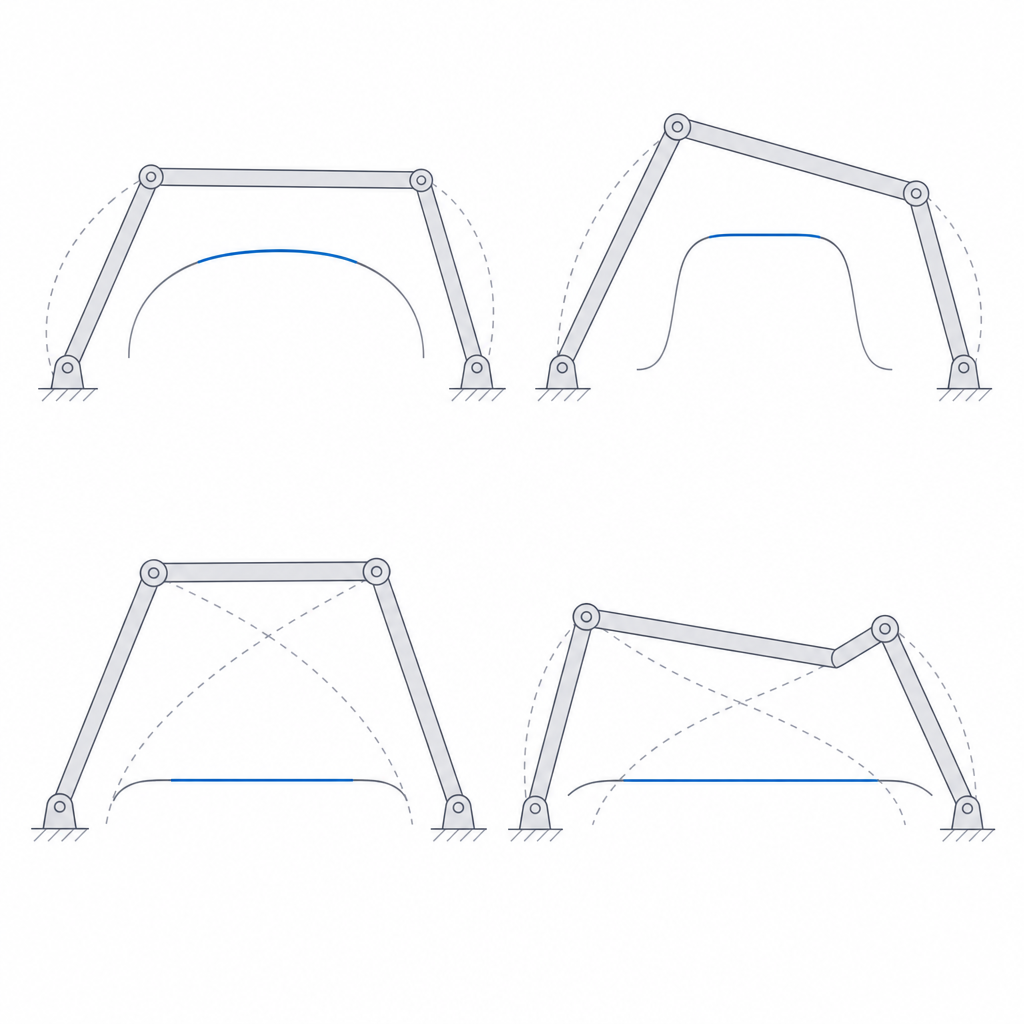
Approximate straight-line motion: the four-bar family (Chebyshev, Watt, Hoeken, Roberts)
To move a point in a straight line, the obvious approach is to give it a rail: a slider, a guide, something that slides. But a printed rail is always a precarious balance between sliding freely and not wobbling: it is full of slop, it wears out right where it works hardest, and it jams at the first speck of dust. There is another way, older and more elegant: chain four bars together with the right proportions and let a point on one of them trace a nearly straight stretch on its own. Nothing slides. Only pivots turn. That is what the Chebyshev family of approximate straight-line mechanisms does, and the key word is approximate: the trick does not give you a perfect straight line, it gives you a line segment that is good enough over a portion of the travel, and the craft lies in knowing which portion that is, and staying inside it.
How four pivots make a straight stretch
A four-bar is the simplest kinematic chain that moves in a controlled way: one fixed link (the frame), two links that pivot on it (the cranks or rockers), and a fourth link joining the tips of the other two, the coupler. Any point on the frame stays still; any point on a crank describes a pure circular arc. The interesting thing happens on the coupler: because its two ends are forced to follow two different arcs at once, the points partway along the coupler do not trace circles but more complex closed curves, the coupler curves. And the beauty of this whole family is that, by choosing the lengths well, part of that curve flattens out until it is indistinguishable from a straight line.
This is not magic, nor something fudged by eye: it is geometry that has been settled since the 19th century. The coupler curve has stretches where its curvature vanishes or nearly so, and there the point advances along a segment that strays from the ideal line by less than the slop in your pins. Chebyshev, Watt, Hoeken, and Roberts are four different proportion formulas for achieving exactly that. They are the same kind of chain — a revolute four-bar — with different length ratios, and each variant optimizes a straight span with a different character: longer, shorter, more symmetric, or with more uniform speed. You change the proportions, not the mechanism.
It is worth nailing down the central idea before we go on, because everything else hangs from it: the straight line exists only over a piece of the travel. The coupler runs along a complete closed curve as the cranks make their turn; the straight segment is a window within that curve. Inside the window, the point stays nearly perfect. Outside, the same curve pulls away quickly and closes back on itself. Designing one of these mechanisms is, in large part, deciding what fraction of the cycle you need straight and choosing the variant and the travel that keep the point inside the useful zone.
Why trade the rail for bars
The underlying reason to prefer this over a slider is physical, not aesthetic. A sliding guide needs clearance to slide: leave no gap and it seizes; leave one and that same gap becomes transverse play, and flat-on-flat contact rubs over its whole surface, packs dirt into the guide, and wears unevenly until the carriage cocks out of true. A train of revolute joints replaces all that with pure rotation around a pin: contact is a small circle, the clearance you need is that of a pivot, not that of a long sliding surface, and nothing sweeps dirt along a channel. In FDM the balance tips even further this way, because a printed slider starts out with its walls thickened inward and its surface stepped by the layering, whereas an isolated printed pivot is exactly the fit we know best how to calibrate. The problem, as you will see, is not calibrating one pivot: it is that four of them stack up in series.
The price of that trade is the one we have already named: the line is approximate and holds only over its span. It is an honest exchange. You give up the geometrically exact straightness of a well-made rail in return for robustness, tolerance to dirt, and a motion that does not jam. For the vast majority of uses — and certainly for almost anything you are going to print — that nearly straight segment is more than enough, and the difference from the ideal line is smaller than the errors your printer introduces by other means.
Which variant to choose, and why
The four formulas are not interchangeable; each gives you a straight segment with different properties, and you choose by what your application needs. The practical criterion is twofold: how much straight travel you want and how you want the point to move along it.
The Hoeken is the most convenient for general-purpose linear guiding, but its appeal is not being the straightest — a well-proportioned Chebyshev matches or beats it in pure straightness — it is that over its span it gives a nearly constant speed: the point not only goes straight, it advances at a uniform rate over much of the travel. That is exactly what you want in a press, a walking mechanism, or anything that has to push evenly. The classic Chebyshev is compact and symmetric, easy to size, and a good starting point if what you want is clean straight motion without demanding the longest possible span. The Watt carries its tracing point at the center of the coupler and traces a figure-eight coupler curve whose central crossing gives a very short but extremely straight segment: you choose it when you need a very short, almost perfect straight segment. The Roberts uses a triangular coupler with the point at the apex, and its straight line ends up below the line joining the two fixed pivots: useful exactly when you need the path outside the frame, with the anchors close together and the long straight line hanging beneath. The choice is set by the geometry of your assembly and the length and quality of straight line you ask for, not by any ranking of better or worse.
Where all this makes sense: walking mechanisms for legged robots; presses and straight-push levers; supports that extend or retract a platform in line; arms that move a tool along a straight path without a rail to guide it; platforms that rise and fall without drifting sideways. The common denominator is always the same: you need linear motion in a place where a slider would be fragile, would foul, or would not fit, and it is enough for the line to be good over the working span.
Printing it without the line going crooked
Here the theory meets the bed, and everything elegant about the coupler curve depends on two very earthly things: that the printed proportions are the ones you designed and that the bars do not bend. The coupler curve is a function of the bar lengths and the pivot positions; any error in those dimensions shifts the curve, and with it the straight segment. That is why the first rule is to respect the proportions of the chosen variant precisely: these mechanisms will not forgive rounding a length because it looks neater. The center-to-center pin distance is the dimension that matters, not the outline of the bar.
The second enemy is pin clearance. Every revolute joint has its play — the gap between the axle and the hole that it needs in order to turn — and that play translates into lost motion (backlash): a small dead movement that pulls the coupler point off its theoretical path right when the chain reverses the direction of the load. With a single loose joint it is barely noticeable; with three or four in series, the plays add up and, above all, get amplified by the geometry: the clearance of the pivot nearest the tracing point weighs far more than that of a short, distant crank, because its movement reaches the tip multiplied by the ratio of arms. It is not a simple arithmetic sum of tenths of a millimeter; it is an error that depends on which joint has the play. That is why "it will wear in" does not cut it here: each pivot needs the minimum clearance that turns freely without wobbling, and that figure comes from calibrating your machine, not from a table, as worked out in Tolerances for moving parts. In a straight-line mechanism, a loose joint in the wrong place is the difference between a clean trace and one that snakes.
And then there is the stiffness of the bars themselves, which acts in two different planes worth keeping separate. In the plane of the mechanism — the plane in which all the joints live and along which the working load runs — the straight path is a property of undeformable bars: the calculation assumes that the distance between the two pins of a link does not change under load. A bar that flexes in that plane changes its effective length and falsifies the curve just as if you had sized it wrong. The defense is to give it depth in the plane of motion — that is the direction it must resist bending — and to orient it with the layers parallel to that plane, so that the working stress runs along the beads, not across the bond between layers, which is what Layer orientation for motion explains. But there is a second mode, easy to forget: out-of-plane load. A printed four-bar train is slender and all its joints share one plane; any sideways push makes the whole chain buckle or twist out of plane, and that degrades the line as much as lost motion does. If the mechanism is going to take side loads, brace it out of plane or, better, double the chain into two parallel planes and mount each joint in double shear, with the pin supported on both sides: a pin held at both ends does not sag.
| Cause | Effect on the path | Defense |
|---|---|---|
| Pin backlash | The point snakes when the load reverses; amplified by the joint | Minimum rotational clearance, calibrated; mind the pivot near the tracing point |
| Bar flexion in the plane | The bar changes effective length and shifts the curve | Depth in the plane of motion, layers parallel to it |
| Out-of-plane buckling | The whole chain cocks under side load | Brace out of plane or double up in a double-shear sandwich |
| Imprecise proportions | The straight window moves or shortens | Respect the center-to-center pin distance, not the outline |
| Travel outside the designed segment | The curve pulls away from straight fast | Limit the stroke to the variant's window |
| Pivot wear | Straightness degrades with use | Snug pivots, pure rotation, durable material and fit |
How a four-bar straight-line guide fails
Knowing how the straight line is built, its failure modes are predictable, and it is worth naming them so you recognize them when they show up. The first is deviation from the straight line, and it has two origins we have already seen separately: the lost motion of the joints, which introduces tremor and dead movement, and the flexion of the bars, which shifts the whole curve. Both produce the same symptom — the point does not follow the line as it should — but they are fixed differently: the play, by tightening the clearances where it amplifies most; the flexion, by stiffening the bars and bracing out of plane. Diagnose them separately.
The second is running outside the valid window. If the mechanism is forced to travel through more angle than its straight window spans, the point leaves the good zone and enters the curved part of the path, where the deviation grows very fast. It is not a failure of the mechanism — it is asking it for something it was not designed to give. Size the travel so the useful stroke sits comfortably inside the variant's window, and leave margin at the ends, because that is where the curve begins to peel away from straight.
The third is peculiar to the four-bar and is the one most often neglected: the dead center and poor transmission angle. The transmission angle is the one formed by the coupler and the output rocker, and it measures how much of the force going in turns into useful motion and how much is lost squeezing the pins. Near the ends of the straight window that angle degrades: the mechanism loses mechanical advantage, loses stiffness, and, under load, can jam or run past dead center instead of pushing. This matters precisely in the uses that justify the family — presses, straight push — because that is exactly where there is load: a long straight span is useless if at its ends the mechanism does not transmit force. Keep the useful stroke in the zone where the transmission angle is healthy, not just where the line is good; the two windows do not coincide entirely, and the one that governs under load is the transmission angle.
The fourth is pivot wear. A mechanism that only barely meets its straightness spec at the start will lose it with use as the pins enlarge their hole and the play grows. In a precision guide this matters: what was a clean trace turns shaky after many cycles. The defense is that of any pivot meant to last — pure rotation, well-chosen clearance, and a material and fit that don't wear the hole open — but here wear does not just loosen the joint: it degrades the very function of the mechanism, which was to follow the line.
When the nearly straight segment is not enough for you — when you need geometrically exact straightness and not an approximation, however good — this family falls short by definition, and you have to step out of it toward the Peaucellier-Lipkin and Hart inversor linkages, which trace a mathematically perfect straight line at the price of several more joints and, above all, of demanding pairs of bars of exactly equal length: that is the real difficulty in printing them, not the link count. But for almost everything you are going to print, a well-proportioned Hoeken, with its pins calibrated as Tolerances for moving parts requires and its bars oriented as Layer orientation for motion asks, gives you a robust, rail-free linear motion that ages far better than any slider.