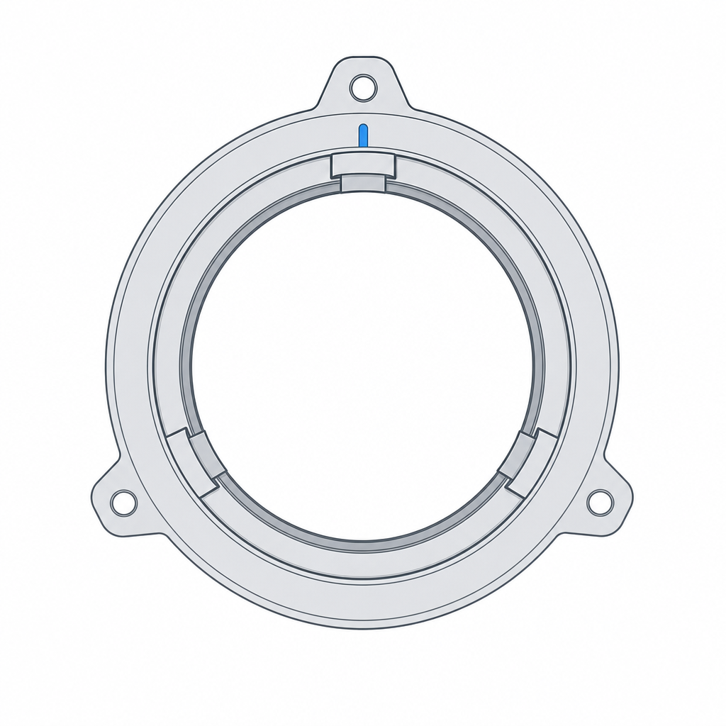
Bayonet mount: insert and quarter-turn to lock
A camera lens doesn't thread on: you push it in straight, twist a quarter-turn, and it seats with a click. That's a bayonet mount, and it's one of the fastest releasable fasteners there is: a single action, no threads to count or cross-thread, repeatable thousands of times. The trick is that the joint does two things in one gesture: it locks against axial pull-out and it tightens against backing-off, all in a quarter-turn of the wrist. And as with almost everything in FDM, what decides whether it turns smoothly or jams isn't the elegant geometry of the L-shaped channel, but a few tenths of clearance and the direction you stack the layers in.
Two gestures in one: the kinematics of the L-channel
A bayonet has two parts that mate by turning. One carries a few protrusions — the lugs, two, three, or four of them, spread around the perimeter; the other carries the channels that receive them. Each channel is shaped like an L lying on its side: an axial leg through which the lug enters straight, parallel to the axis, and a tangential leg along which the lug runs as the part turns.
The gesture matters because the kinematic trap is in the corner of the L. While you push axially, nothing holds: the lug rides up the entry slot and could come back out the way it came. The moment you twist, the lug leaves the axial slot and enters the tangential leg, and now it can't be pulled out: to extract it you'd have to walk the L backward, twist first and then pull. A purely axial tug hits the roof of the channel. That's the whole magic: extraction and locking are in perpendicular directions, so the motion that closes is not the motion that opens.
What's missing is the clamp. A flat L-channel would leave the lug loose in its tangential leg, rattling. That's why the final leg isn't horizontal: it rises slightly — a gentle ramp — or drops into a detent. If it's a ramp, as you turn, the lug climbs it and takes up the axial clearance, so that at the end of travel the two parts are pressed firmly against each other; the ramp converts turning torque into axial clamping force, just as a screw converts rotation into linear travel, only in a quarter-turn instead of several.
The slope of that ramp sets two things at once, and the two are worth keeping apart. A steep slope clamps a lot per degree of turn, but it also releases easily: friction isn't enough to hold it and the joint tends to loosen on its own. A shallow slope clamps little per degree, but it approaches the self-locking condition — like a fine-pitch screw that won't back-drive itself; the price is that, if friction is high, that same shallow ramp digs in and is hard to overcome, binding up before reaching the stop. The sweet spot is a ramp that clamps just enough without digging in, and which precisely because it isn't fully self-locking needs a detent to fix it.
The detent: what keeps the bayonet from backing off
The ramp clamps, but on its own it doesn't stop the joint from turning back and releasing. Any vibration, any rub, slowly undoes the quarter-turn in the opposite direction, and the clamp you gained with the ramp you lose little by little. The detent is what stops this: a small depression — or a small bump — right at the end of the tangential leg; the lug drops into it with a click as the turn finishes.
Physically it's a local minimum. To back out, the lug would have to climb the detent step again, and that demands a torque that vibration doesn't supply: the joint settles into its valley. That audible click isn't a flourish — it confirms the lug has cleared the step and dropped into the retained position. A bayonet with a detent survives vibration; one without it loosens with use, and it's exactly the failure mode that surprises people most, because the part assembled perfectly and then disassembles itself in service with no one touching it.
For that click to exist you need one thing that's easy to overlook: elasticity. The lug only drops into the valley and climbs the step again if something gives and recovers — the channel wall flexes a little as it passes the bump, or the lug arm bends and springs back. A detent cut into two perfectly rigid parts with no clearance won't click: either it won't go in, or it presses and stays jammed for good. Design it as a depression the lug overcomes with resistance, counting on a thin wall to absorb that interference and return to place. The opposite would be a wall that stops it dead; that's an end-of-travel stop, and you want both: the detent retains against backing-off, and a stop at the end of the channel keeps you from turning further and overrunning the tangential leg. Without a stop, excess torque drags the lug past the detent and leaves it in no man's land, neither locked nor free.
Spread the lugs: symmetry isn't just for looks
The beginner's temptation is to solve the bayonet with a single large lug and its one channel. Don't. A lone lug concentrates all the clamping force at one point of the perimeter, and that fails on two fronts at once: it rocks the joint, because it pulls on one side and leaves the opposite side loose, so the two parts seat crooked; and it loads that single lug with the whole effort, driving it toward fatigue failure every time you turn under load.
Spread two, three, or four lugs symmetrically around the perimeter. With the load distributed across equidistant points, the clamping forces balance around the axis and the parts seat flat, without rocking; and each lug carries a fraction of the effort, so none of them works at the limit. Three is the classic number on camera lenses for a reason: three points define a plane unambiguously, so three lugs share the clamp and leave the seat flat and deterministic, without over-constraining it. Two work for small, lightly loaded joints; four, when the axial load is high and you want to lower the effort per lug.
Watch out for a common confusion: three equally spaced lugs don't fix a single angular orientation. The part fits equally well in three positions 120° apart, so symmetric spacing gives you a flat seat, but it doesn't tell you which orientation it enters in. You get angular uniqueness — making the bayonet mount only one way, to align contacts or marks on a lens — by deliberately breaking the symmetry: make one lug wider, or change one spacing, and only one orientation will fit. It's keying by geometry, for free — you do nothing more than make one lug different from the rest.
Clearances: the channel has to let the lug run
This is where it's decided whether the bayonet turns smoothly or seizes, and the reasoning is the same one that governs any moving part. The lug has to run through the channel, not press-fit into it, so you need clearance in both directions of motion: axial, so it enters the slot without forcing, and tangential, so it turns through the L leg without rubbing against the channel walls.
For the tangential leg — the one that defines the seat and where excess gap turns into rattle — a reasonable starting value is 0.15–0.25 mm of gap per side: a genuine sliding fit, it turns freely but without play. The axial entry slot allows more room, 0.3–0.4 mm per side, because there all that matters is that the lug passes straight without forcing and the play doesn't compromise the seat. And count on the printer eating part of that gap: a printed channel comes out narrower than you drew it, because the bead width pushes the walls into the gap, exactly the same shift that narrows any printed hole. The criterion for how much gap to leave according to function — which here is "turns freely but without play" — comes from the same calibration as any other fit; it's worked out in Tolerances for moving parts.
There are two dimensions the channel drawing doesn't show that break a printed bayonet more often than anything else. The first: the axial entry leg has to be longer than the height of the lug, with a couple of layers of margin, so the lug fully clears the lip of the channel before it begins to turn; if you come up short, the lug turns while catching on the lip and never makes it into the tangential leg. The second: the wall over the roof of the channel — the material that covers the tangential leg from above — needs ample thickness so it doesn't sag when printing the overhang; below two or three perimeters, that roof slumps and stops acting as a stop against the lug.
And the detent is the exception to all this clearance: there you don't want loose gap, but a controlled interference that the wall flexes and absorbs. The clearance runs along the path — entry and turn; the interference fit lives only in the final position. If you give turn clearance to the detent as well, the click drops to a whisper and you lose the retention. Treat them separately: the channel, loose; the detent, with just enough interference for a thin wall to flex and absorb.
| Zone | Clearance | Why |
|---|---|---|
| Axial entry slot | 0.3–0.4 mm/side | the lug enters straight without forcing; the play doesn't affect the seat |
| Tangential leg (turn) | 0.15–0.25 mm/side | runs through the L without rubbing and without play; defines the seat |
| Clamping ramp | gentle slope | converts turn into clamp; too steep loosens on its own, too shallow digs in |
| Final detent | interference the wall flexes to absorb | retains against backing-off; the click confirms |
Print orientation: the channel roof decides
The plane that decides whether a bayonet comes out clean is the roof of the L-channel, the upper surface of the tangential leg, against which the lug pushes as it clamps up the ramp. That roof is an overhang relative to the print axis: it's material hanging over the gap of the channel, with nothing beneath to hold it while it prints. And a badly oriented overhang comes out drooping, with a rough surface right where the lug has to slide.
The orientation that almost always works best is to print with the axis vertical, the part standing upright on the bed. That way the lugs and channels develop in horizontal planes, layer by layer, and come out cleaner and more circular — the same reason a hole printed vertically comes out more cylindrical than one lying down. The price is that the roof of the channel becomes a horizontal overhang, and that roof isn't just any surface: it's the functional face the lug clamps against. If you resolve it as an unsupported overhang, the layer stepping degrades the clamping contact, not just the finish. The correct outcome is to give it a printable chamfer, around 45°, that the slicer can build without support and without stepping; don't accept a stepped roof as equivalent, because there the roughness is load, not cosmetics.
This is the orientation side of the same problem that governs any printed mechanism: you decide where the weak planes and the overhangs fall by how you place the part on the bed, and that decision counts for as much as the geometry of the channel. The lug, moreover, works in bending and shear at its base when it holds the axial load — it's a cantilever beam loaded at the tip — so you want its beads not stacked right on the plane that gets stressed most; standing it upright usually leaves it on the favorable side. The full criterion for how to orient a part according to which way you load it is in Layer orientation for motion.
A bayonet mount is, at heart, a sliding fit with memory: two parts that run over each other with clearance and that a detent fixes in just the right position. Get the channel's clearances and the layer direction right, and you'll have a fastener that mounts with one gesture and survives vibration; get them wrong, and you'll have a jam or something that loosens on its own. To nail those clearances before printing the whole assembly, start by measuring your machine: Tolerances for moving parts takes you from the intended function to the actual gap.