Helical compression spring: the classic printed coil
Printing a helical spring is one of those things that looks great on screen and holds up badly in the hand. The coil comes out beautiful, compresses with a touch that feels real, and by the third sustained load it has lost half its travel or split open between two layers like a clean crack. The problem isn't the drawing. You're asking a stack of welded beads to work in exactly the direction where it's weakest. A spring is a coiled wire that returns energy in torsion, and in FDM that wire isn't wire: it's low-modulus plastic and, above all, anisotropic. Understanding what governs its stiffness and where it breaks is what separates a soft return that lasts from a decoration that relaxes in an afternoon.
Stiffness lives on the fourth power
The spring rate of a helical spring isn't a number you choose, it's one that falls out of four variables, and none of them weighs what intuition says. Stiffness rises with the material's modulus and with the wire diameter to the fourth power; and it drops with the mean coil diameter cubed and with the number of active coils. In compact form, k ∝ G·d⁴ / (D³·N). That fourth power is the brutal lever: a wire 20% thicker doesn't stiffen by 20%, it stiffens by a little more than double (1.2 to the fourth is 2.07). If your spring comes out soft, thickening the wire by a tenth does more than adding five coils.
The physical reason is in how the material works. When you compress the spring axially, each stretch of wire doesn't compress: it twists. The axial load translates into a torque that travels the whole coil, and the deformation is stored as shear in the cross-section. That's where the two exponents come from. The d⁴ comes from the torsional stiffness of the circular section itself, which grows with the fourth power of its diameter. The D³ comes from somewhere else: a wider coil gives the load more leverage (one factor of D) and, at the same time, lengthens the coiled wire (another factor of D), and that longer wire accumulates more twist for the same torque (a third factor of D). Multiply the two causes and you get the d⁴/D³. Travel is shared among the turns: the more active coils, the more places to accumulate twist, and therefore a softer spring with longer travel.
There's one parameter worth keeping in mind even though it doesn't appear in the formula: the spring index, the ratio between the coil diameter and the wire diameter (D/d). When that index is low — very tight coils, fat wire on a small coil — the curvature concentrates stress on the inner face of each coil. And the inner face is exactly where, in a printed part, a layer opens up first. An index that's too low isn't just hard to print clean: it loads the weak plane where it hurts most.
And here comes the first FDM warning: the formula assumes a known, constant modulus. In a printed part the effective modulus of the "wire" depends on how the bead is laid down in each section and on how the layers weld to each other, so the real stiffness deviates from the theoretical one, almost always on the low side. The formula gives you the trend and the order of magnitude; the fine number comes from the part printed and measured.
From force to travel: linear until the coils touch
A compression spring does one very specific thing: it converts an axial force into a linear displacement, and it does so with an almost straight force-travel curve. Push with twice the force and it sinks twice as far. Up to a limit. That limit is coil bind (solid height): when the turns touch each other, the spring stops being a spring and becomes a solid cylinder. The curve, which had been a gentle ramp, shoots vertical all at once. Past coil bind you no longer store energy, you compress plastic against plastic.
That linearity is what makes a cylindrical spring predictable, and sometimes it isn't what you want. If you coil the wire into a cone or with variable pitch, the curve stops being straight: the larger-diameter coils, more flexible, give way first, and as they flatten, stiffer material comes into load. The result is a progressive response — soft at first, hard at the end — that absorbs small bumps gently and big ones without bottoming out. The cone also has a geometric advantage that's welcome in FDM, but with one condition: if you design each coil to nest inside the one before it — a diameter smaller than the inner gap of the turn around it and a coil height that doesn't exceed the wire thickness — then on compression the spring collapses almost flat, which reduces the solid height and frees up much more usable travel in the same volume. A generic cone won't do this on its own: if the coils butt radially or the wire doesn't nest, it binds as soon as any other.
When plastic works and when you need steel
It's worth being honest about what a printed spring is good for. It's more than enough for a long-travel, modest-force return — a lid that springs back into place, a button that recovers, a mechanism that needs gentle, constant push — for soft cushioning, and for prototypes where you want to validate geometry and feel before buying anything. In all those cases the printed spring is the cleanest solution: zero hardware, zero assembly, one monolithic body that comes off the bed ready.
Where it doesn't work is where force and service life really matter. A printed spring under sustained load creeps and relaxes: loaded plastic lets the stress flow off slowly, and what pushed hard on day one pushes with half the force weeks later. For preload that has to last, or for thousands of cycles at real force, the right answer is almost always to embed a metal spring and let the printed part be only its housing and its guide. That's not giving up: it's putting each material to do what it knows. How to integrate that steel spring — its seat, its guide, its preload — is the same problem as any other metal component inside an FDM part, and it's covered in Embedded hardware: magnets, bearings, and inserts.
Orientation decides almost everything
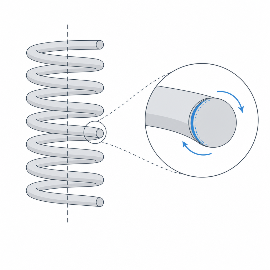
Here's the trap that ruins most printed springs, and it's a process trap, not a calculation one. An FDM part is anisotropic: strong along the beads, weak between layers, where only the weld of one layer to the next holds it (developed in Layer orientation for motion). A spring works in torsion at every stretch of its wire, and that torsion generates stresses that, depending on how you orient the part, land squarely on the weak plane.
If you print the spring standing up, with the helix axis vertical, the layers stack perpendicular to that axis and each coil is cut by horizontal layer planes. On compression, the wire's torsion pulls precisely to separate those layers: the spring delaminates, opens between two beads like a zipper, and it does so early and without warning. Laying the part down doesn't eliminate the problem, and it brings a cost in return: you change which layer planes end up loaded, but the helical geometry makes the wire cross the layer planes at some stretch of every turn, so there's always material working against the weld. At low pitch, with the axis horizontal, a good part of the wire runs near the bed plane, along the beads, and the critical fraction loaded in peel is appreciably reduced; but in return you need supports that mark the coil surface and create new failure planes. There's no magic orientation that puts the whole helix in the strong plane; all you choose is how much of the coil is compromised and what you pay to reduce it.
That's why the material weighs as much as the orientation. A wire with good elongation before breaking tolerates the interlayer weld working under load without cracking: TPU, PP, and nylon comfortably beat PLA, which is rigid and brittle and opens between layers at the first serious cycle. TPU is also elastic by nature, so it absorbs deformation where PLA would accumulate stress until a layer breaks. And there's an unavoidable resolution limit. A thin wire — exactly what the fourth power pushes you to avoid if you're after force — can fall below what your nozzle resolves with several beads, and it comes out hollow, irregular, or unwelded between turns. The opposite extreme fails too: if the pitch is too small for your nozzle, the coils fuse together and the spring comes out solid, a cylinder that doesn't flex. Between those two limits — wire too thin to weld, pitch too fine that welds too much — is the window in which a spring actually comes out.
Printing it to last
A spring is one of those parts where the slicer settings weigh as much as the geometry, because anything that improves the weld between layers attacks the dominant failure mode directly. The first thing is wire thickness: don't let it drop below three or four extrusion widths, so the section is formed by full perimeters and not by infill, which on such a small section comes out poor. Print the wire all perimeters, with 0% infill: the number of contours should cover the thickness side to side. A fine layer height increases the number of welds per unit length and improves the overlap between beads, exactly where the torsion wants to open. And since delamination is an adhesion problem, play in its favor: extrusion temperature at the high end of the material's range, low speed on the perimeters, and the fan at just the minimum the geometry tolerates without deforming. Each of those settings buys a few more newtons before the first layer gives way.
The three failure modes, in order of probability
A printed spring fails in three ways, and it's worth recognizing them because each is fixed differently.
The dominant one in rigid plastic is delamination between layers in the coils: the torsion opens the interlayer weld and the crack runs clean between two beads. It's the failure we just saw, and it's fought with material and orientation, not by thickening — a thicker PLA wire badly oriented opens just the same, only later. The real defense is an elastic material, a careful layer weld in the slicer, and accepting that the helix is never entirely in the strong plane.
The second is creep and relaxation: under sustained compression, the plastic gives way slowly and the spring loses force and free height over time. It doesn't break; it surrenders. PLA is among the worst here despite its rigidity, and service heat speeds it up. But beware the easy conclusion that "elastic material" solves it: TPU beats delamination, but its remaining deformation under sustained load (compression set) is usually worse than PLA's. A TPU spring compressed for days also loses height and force, sometimes more. For a soft, intermittent return it works; for a preload that lives permanently compressed, it doesn't. The only real cure for lasting preload is embedded steel.
The third is lateral buckling: a slender spring — lots of free height for little diameter — doesn't compress straight, it bows to one side and slips out of place. It's pure compressed-column geometry, not an FDM defect, but the plastic's low modulus makes it appear sooner than in an equivalent metal spring. The rule of thumb: watch the ratio of free height to mean diameter (Lf/D). Above 4 with loose ends — and already close to 2.6 if the ends are flat and guided — buckling is likely. If you land there, give it a guide: a central rod on the inside or a cylinder on the outside that keeps it from bowing. Without a guide, a slender spring turns the axial load into a sideways whip long before it reaches its usable travel.
| Need | Recommendation | Why |
|---|---|---|
| Soft return, long travel | Print in TPU/nylon, not PLA | the elongation tolerates the interlayer torsion |
| High force or many cycles | Embed a steel spring | the plastic creeps and delaminates |
| Preload over days | Embedded steel, no alternative | creep robs force, and TPU deforms too |
| Progressive response / flat collapse | Telescoping cone or variable pitch | the flexible coils give way first |
Slender spring (Lf/D ≳ 4) |
Add a central or external guide | prevents lateral buckling |
If the conclusion is "I need real force and I need it to last," the spring stops being a printed part and becomes a steel component inside your design: the work shifts to housing and preloading it well, which is exactly what Embedded hardware: magnets, bearings, and inserts is about.