Special linkages: the exact straight line (Peaucellier, Hart) and spatial motion (Bennett, Bricard)
A four-bar gives you an approximate straight line: the midpoint of a Chebyshev coupler traces a nearly straight segment and then drifts away, because the curve it draws is a sextic and only touches the line tangentially at a few points. For almost everything, that's enough. But there are two cases the ordinary plane can't reach, and both sit at the edge of what a bar mechanism can do: the mathematically exact straight line — a true straight path, not one that merely resembles it — and out-of-plane motion, a closed chain that moves and folds in 3D space. These are the Peaucellier-Lipkin and the Hart on one side, and the Bennett and the Bricard on the other. We include them with a warning that applies to all four: they are the mechanisms FDM penalizes hardest, because the one thing each of them does well depends on the tenths of a millimeter of clearance your printer doesn't control.
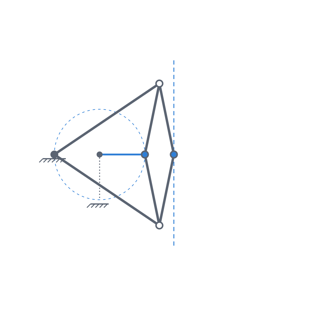
The exact straight line comes from inverting a circle
In 1864 the Peaucellier-Lipkin linkage solved a problem that had stayed open for nearly a century — Watt's problem, posed around 1784: tracing a perfect straight line with hinged bars, with no guides and no surfaces. It does this by physically realizing a geometric inversion, the transformation that takes a point at distance r from a center to another point at distance k²/r along the same radial line. The key to that transformation is that it turns circles passing through the center of inversion into straight lines. So if you force the input point to travel an arc of a circle that passes through the center of inversion, the inverted output point is forced to travel an exact straight line. Not approximate: exact, because it is the algebraic consequence of the inversion, not a curve happening to fit closely.
What forces the input point along that arc is a single crank bar anchored to a fixed pivot, and here the first critical dimension appears: the circle the input describes passes through the center of inversion only if the length of the crank is exactly equal to the distance between its pivot and the center of inversion. That equality is not an assembly detail, it is what produces the straight line. Get it wrong by a few tenths of a millimeter and the arc stops passing through the center, the inversion stops mapping that circle to a line, and what you trace is a smooth curve that merely resembles one.
The assembly that materializes the inversion is a rhombus of four equal bars hinged at its four corners, with two longer, equal bars joining a pair of opposite corners of the rhombus to a fixed point. That symmetry guarantees that the input point, the output point, and the fixed pivot always stay collinear and that the product of their distances stays constant: that is the inversion. Counting the input crank, this comes to seven moving links and six revolute joints. The Hart does the same thing with fewer bars — a four-link contraparallelogram instead of the rhombus-plus-bars assembly — at the cost of a geometry that is harder to tune. Both are the historical solution to the straight-line problem, and the difference from a Chebyshev is not one of quality but of kind: the Chebyshev imitates the straight line, the Peaucellier generates it.
When approximate isn't enough
The reason to pay the cost of an exact linkage is narrow, but real: when the deviation of an approximate tracer takes you out of tolerance. A Chebyshev or a Watt draws a straight line with a residual error that grows toward the ends of the stroke; on a short, undemanding guide that error disappears under the general slop of the assembly. But on a precision guide, on the carriage of a measuring instrument, or anywhere straightness is the specification and not a decoration, that residual error is the limit of your part. That is where the exact linkage stops being a textbook curiosity and becomes the only bar topology that gives you a straight line without resorting to a sliding rail — which is exactly what a bar mechanism is meant to avoid, because it drags friction, wear, and a surface to maintain.
The arithmetic is simple: if the error of a Chebyshev over your stroke is smaller than the backlash FDM is going to introduce into your pivots, the exact linkage buys you nothing and costs you three extra links. It only wins when your straightness requirement is finer than the play introduced by the rest of the mechanism. Before you choose it, measure that complete error budget, because it's almost always the backlash — and not the topology — that sets the straight line you actually get.
Spatial mechanisms move only when their axes are tuned to each other
Now a different problem. A closed quadrilateral of four bars joined by four revolute joints is, in general space, an overconstrained structure: the Grübler-Kutzbach mobility criterion assigns it M = 6(n−1−j) + Σf = 6(4−1−4) + 4 = −2 degrees of freedom, and a negative number predicts not merely that it won't move, but that it has too many constraints. Yet the Bennett moves. It is a closed chain of four links with four revolute joints whose axes are neither parallel nor concurrent, and which despite the arithmetic has one degree of freedom. The trick — because it is one — is that this is not a generic mechanism: it moves only if its bars and its axes satisfy certain specific geometric relationships. Opposite links of equal length (a₁ = a₃, a₂ = a₄), equal opposite twist angles (α₁ = α₃, α₂ = α₄), zero offsets along the axes, and the closure condition that ties them all together: sin α₁ / a₁ = sin α₂ / a₂. The mobility doesn't come from adding joints: it comes from the geometry being tuned so that those constraints, instead of being independent and locking up, overlap and leave one mode of motion free. The −2 deficit Grübler predicted is exactly what the geometric tuning cancels to return 1 degree of freedom. That is why these mechanisms are called paradoxical or overconstrained.
The Bricard carries the same idea to six links: a family of mechanisms with six revolute joints — line-symmetric, plane-symmetric, trihedral, and the other types — that move for the same reason, with axes oriented in 3D under relationships that turn an apparently overconstrained chain into a one-degree-of-freedom mechanism. Don't confuse them with the flexible Bricard octahedron, which is a related but distinct object: a polyhedral surface that flexes, not a chain of bars. The practical consequence of the six-bar family is what makes it valuable: the motion is no longer confined to a plane. A Bennett sweeps a spatial path; a network of Bennett or Bricard mechanisms deploys and folds in 3D. That is why they are the basis of deployable structures, of folding mechanisms, and of joints that have to take motion out of the print plane — things no planar chain can do, however you arrange its joints.
FDM penalizes exactly what these mechanisms provide
Here is the problem common to both families, and why we bring them with reservations. What a Peaucellier provides is exactness; what a Bennett provides is spatial mobility. And both things depend on simultaneously holding precise angles at many pivots at once — the Peaucellier has six joints, the spatial ones have axes oriented in 3D that each have to be held to their exact angle. That is exactly what FDM is worst at.
The first enemy is the accumulation of backlash. Each printed pivot carries its own play, and that play adds up along the chain. In an exact tracer, the play in the pivots shifts the rhombus points away from their theoretical positions; because the linkage geometrically amplifies the input motion, that play translates into a path error that may be larger or smaller than the nominal play depending on position along the stroke, but that in any case breaks the constancy of the product of distances and curves the line. The linkage degrades to approximate and loses its only advantage over a Chebyshev, which is simpler and tolerates that same play far better. You've paid three extra bars to end up with the straight line of a four-bar tracer.
For the exact straight line, the recipe is demanding and points in one direction only: tight pivots and rigid bars, at the bottom of the clearance range, far from the generous play you'd allow for a coarse, low-precision pivot — you decide that with the clearance budget from Tolerances for moving parts, knowing that here you work at the bottom of the range, not in the middle. Bar rigidity matters as much as the pivot, because a bar that flexes under load misrepresents its length just as a pivot with play misrepresents its position, and the linkage only delivers an exact line on exact lengths.
But that recipe opens a manufacturing conflict you can't ignore. Printing a slender, rigid bar calls for laying it down with its long dimension in the bed plane and the fiber following the axis, not stacked between layers, as Layer orientation for motion details: loaded along the layer line it flexes and delaminates exactly where it hurts most. Except that laying the bar down leaves the pivot holes with their axis horizontal, parallel to the bed, which is the worst possible orientation for a hole — elephant's foot at the mouth, an elliptical cross-section, and an overhang at the top of the bore. A hole printed with its axis vertical comes out round and tight; a horizontal one comes out oval and with more play. So the orientation that gives you rigid bars is exactly the one that worsens the pivots you wanted tight. There is no clean answer: you'll have to split the compromise, almost always laying the bars down and recovering the roundness of the holes with a reamer or a quick pass by hand.
Spatial mechanisms need the opposite: clearance, not tightness
For the spatial mechanisms the recipe inverts, and this is the easiest mistake to make when jumping from one family to the other. A Bennett or a Bricard is overconstrained: hypersensitive to manufacturing errors at every joint at once, because each badly pinned axis fights the others. If on top of that you tighten the pivots to minimum play, you have no margin to absorb those orientation errors, and the mechanism locks up through interference between links — it seizes, not because it has excess mathematical constraint, but because the real geometry no longer closes and the parts push against each other.
The pragmatic way out is the opposite of the linkage's: deliberate clearance in the joints, slightly underconstrained, so that the play in each pivot absorbs the axis orientation error and the mechanism moves despite not being geometrically perfect. You pay for that motion in precision — a Bennett with play sweeps a slightly ragged path — but a mechanism that moves with clearance is worth more than one that's perfect on paper and comes off the bed as a solid block. Go up within the clearance range instead of down, the reverse of the exact straight line.
Orientation comes into direct conflict here with the rule of laying the part flat: in a spatial mechanism, a joint axis leaves the plane of the bed by its very nature, and you can't make them all horizontal or all vertical. You'll have to choose which axis you sacrifice to the overhangs and which you protect, because you'll rarely be able to orient them all well at once — one more reason to give them clearance, which forgives what orientation can't fix.
Failure modes: the straight line curves, the spatial one locks up
It's worth naming the two failures separately, because they are different and are diagnosed differently.
The exact straight line's failure is silent: the mechanism assembles, turns, and traces something resembling a straight line, but the moment there's backlash or flexion that line becomes approximate. Nothing breaks, nothing jams — it simply loses the property you chose it for, and you end up with a seven-link linkage that performs like a four-link tracer. The failure is one of performance, not of function, and that's why it's treacherous: you discover it by measuring the path, not by looking at the mechanism. If you're not going to measure straightness, you have no way to know the Peaucellier has stopped fulfilling its only reason for being.
The spatial one's failure is loud and categorical: if the printed axis angles drift away from the geometric condition and you didn't give them clearance to absorb it, the mechanism doesn't degrade gradually — it jams or goes rigid. It goes from one degree of freedom to zero. You notice it on the first attempt to move it, because it won't move. It is the more obvious of the two failures, but the less forgiving: there's barely any margin between "works" and "is a solid block," and that margin is set by a few degrees in the orientation of the joints that FDM doesn't guarantee without a careful assembly — or without the clearance that absorbs it.
| Family | What it provides | Critical sensitivity | Clearance recipe | Failure mode |
|---|---|---|---|---|
| Peaucellier-Lipkin | Exact straight line through geometric inversion | Constancy of the product of distances; crank = pivot-to-center distance | Bottom of the range: tight pivots, rigid bars | Backlash curves the line; degrades to an approximate tracer |
| Hart | Exact straight line with fewer links | Contraparallelogram geometry, harder to tune | Same as Peaucellier, with less margin | Same as Peaucellier |
| Bennett | Spatial 1-DOF motion with 4 bars | a₁=a₃, a₂=a₄; α₁=α₃, α₂=α₄; sin α₁/a₁ = sin α₂/a₂ | Top of the range: deliberate clearance to absorb axis error | Drifted angle, no clearance → locks up |
| Bricard | Spatial folding and deployment, 1-DOF with 6 bars | 3D orientation of the six axes | Same as Bennett: generous clearance | Same: loses mobility and seizes |
Treat them for what they are: showcase mechanisms, the step you climb only when the approximate straight line of a Chebyshev or the plane-confined motion of a four-bar isn't enough for you. When you choose them, assume that FDM is worst at the very thing they stake their value on — the exactness of the lengths in the linkage, the precision of the axes in the spatial one — exactly what a filament printer controls worst. And remember that the discipline that saves them is not the same for the two families: for the exact straight line, the bottom of the clearance range from Tolerances for moving parts and bars as rigid as you can make them; for the spatial one, the opposite, generous clearance that absorbs the orientation error the bed can't pin. The layer-orientation rule from Layer orientation for motion applies to both, and in both it forces a compromise between bar rigidity and pivot roundness that you'll have to split by hand.