Detent hinge: holding at defined angles
A plain hinge holds its angle by friction: leave it where you let go and it stays there until something pushes it. A detent hinge does something different, and more useful when you need repeatable positions: it doesn't stay where you let go of it, but instead drops with a click into one of several predefined angles and resists being moved out of them. Think of a stand that has to sit at 30, 45, or 60 degrees and nothing in between; a folding bracket that always returns to exactly the same position; a rotary knob with stops you feel under your fingers. What turns an ordinary hinge into a detent one is a notched track and an elastic follower that drops into it, and packing those two elements into a single printed part is where the hard design decisions start.
How it clicks into place: the track and the follower
The mechanism is a cam follower riding on a toothed track. One of the hinge's two halves carries a ring or sector, fixed to the axis of rotation, with notches cut at the angles you want to hold; the other carries an elastic follower — a printed tab that flexes, or a ball pushed by a spring — that travels along that track as it turns. Between one notch and the next the follower rides compressed against the crest, storing elastic energy; when the rotation carries it over a notch, the follower relaxes by dropping in and releases that energy all at once. That is the click: not a decorative sound, but the follower recovering its shape and pushing the hinge toward the bottom of the notch.
Two design consequences follow immediately. The first is that the number and spacing of the notches are your available angles, no more: if you want stops at 0, 45, and 90 degrees, you cut three notches at those three angles and nothing in between holds. The second is that retention isn't free in either direction of rotation: to get out of a notch you have to compress the follower again by climbing it up the flank, and that is exactly the force you feel as resistance. A well-made detent hinge is easy to move between positions and firm in each position, and the same notch geometry governs both.
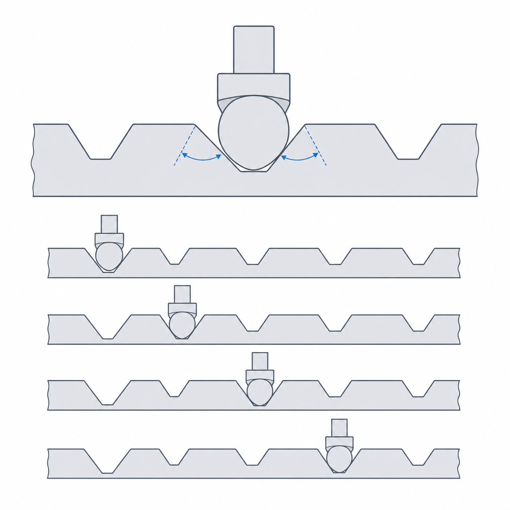
The flank angle sets the firmness
The most important face of each notch is the flank: the ramp the follower climbs to get out. Its slope decides how much force it takes to change position — it is purely a question of how the turning force resolves into the direction that compresses the follower. With a shallow flank — a shallow notch with gentle walls — the turning torque converts easily into the component that compresses the follower: it leaves the notch with little effort and the transition between angles is soft, a step you barely feel. With a vertical flank — a deep notch with steep walls — almost all of the turning force goes into pushing the follower against a wall that barely moves it aside, so the position is very firm and hard to break out of, but you pay for it with a much higher changeover torque.
There is no "correct" flank: there is a trade-off that depends on how the hinge is used. A knob you'll turn often with your fingers wants soft flanks; a bracket that has to hold the weight of a lid without dropping wants steep flanks. And there is a physical limit to raising firmness: a flank that is too vertical no longer retains — it locks — because the follower can't climb it without deforming past its elastic limit, and then either the hinge won't move or the follower yields plastically and the click is lost for good. Useful firmness lives in the range where the flank is hard to climb but still climbable.
One decision a stand makes obvious is whether the two flanks of each notch should be the same. A symmetric notch retains equally in both directions of rotation; an asymmetric notch — a gentle entry ramp, a steep retaining flank — assembles and changes smoothly on one side but holds firm under load on the other. For a stand that always carries weight in the same direction, asymmetry is the standard approach: you put the steep flank on the side the weight pushes against and leave the entry side gentle so adjustment is comfortable. You only need symmetric flanks when the load can come from either side.
Two opposing clearances in the same part
Here is the conflict that makes this hinge hard. The pivot and the detent demand contradictory things of the same part. The pivot is a joint: it needs clearance to rotate freely, gap on each side of the axis so it doesn't seize, the sliding fit your printer can give. The detent is exactly the opposite: it needs the follower to make precise, firm contact with the notched track, with no unwanted play, because any slack between the follower and its track eats into the effective notch depth and softens the click. One part needs loose where it rotates and tight where it retains.
The trap is that the pivot's play doesn't stay in the pivot: if the axle wobbles inside its hole, the follower moves away from and toward the track depending on which way the wobble carries it, and the click turns irregular — firm at one point in the wobble, nonexistent at another. So it's worth treating the two clearances as two independent calibrations and not inheriting one from the other. The pivot is sized with the sliding gap you measured following Tolerances for moving parts; the follower-track interference is tuned separately. Almost always you load the interference onto the follower, which is elastic and absorbs the mismatch, rather than onto the track. And it helps if the follower pushes in a direction that seats the axle against one side of the hole instead of letting it float: a pivot preloaded against a wall has almost zero effective play even if its nominal clearance is generous, and that stabilizes the detent without seizing the rotation. That preload is exactly what lets you use the high end of the clearance range without the wobble ruining the click.
| Zone | Requirement | Starting fit |
|---|---|---|
| Pivot (axle in hole) | Free, smooth rotation | 0.15–0.25 mm/side, sliding; the high end only with the axle preloaded against a wall |
| Follower against the track | Firm contact, no play | No clearance; load the interference onto the elastic follower |
| Notch (bottom and flanks) | Clean seating of the follower | Model the notch on the follower's real width, not the nominal one |
Printing the follower: orientation and thickness
This hinge combines the two orientation problems you already know separately, and they have to be solved at once on the same part. The first is the printed spring. If the follower is a tab that flexes, it's a cantilever, and it delaminates just like any badly oriented snap-fit. Print it on edge, with the layers stacked in the bending direction, and the outer fiber at its root lands on the weak plane between layers — so it opens like a crack within a few dozen clicks, or on the first one. The rule is the same as in Snap-fits that won't release: lay the spring so it flexes in the plane of the layers, following the beads, not peeling them apart. If you embed a metal spring-loaded ball instead of printing the spring, this problem disappears — steel doesn't delaminate — and you trade it for the problem of housing the hardware, which is the one in Embedded hardware: magnets, bearings, and inserts.
The second problem is the notched track. A notch is a void, and depending on how you orient the track its flanks can end up as unsupported overhangs the printer has to bridge in the air: they come out drooping, stepped, and coarse, and a rough notch flank turns a clean click into a gritty drag that also speeds up wear. Orient the track so the notch flanks print as supported walls or, at most, overhangs above your material's safe angle, not as mid-air bridges. Often you won't be able to optimize the spring and the track in the same print orientation, and then you have to decide which one to sacrifice: it's almost always worth protecting the spring from delamination, because a delaminated spring kills the whole hinge while a slightly coarse flank only makes it rough. All of this is the detail of Layer orientation for motion applied to a part that asks for two incompatible things.
The thickness of the spring matters as much as its orientation. A cantilever that's too thin — one or two perimeters — flexes outside the elastic range and fatigues in few cycles; too thick, it doesn't flex and it scrapes or locks instead of clicking. Aim for a spring of three perimeters minimum, on the order of 1.2 to 2 mm thick for a 0.4 mm nozzle, and model it so it prints with continuous perimeters along the tab, not with infill: what carries the bending is the fiber running the length of the arm from root to tip, and a spring filled with internal zigzag breaks where the infill doesn't stitch.
What breaks it over time
A detent hinge ages through three characteristic failure modes, and all of them are progressive: they don't fail all at once, they degrade until one day you notice it no longer clicks. The first is wear of the contact pair. Each time the follower climbs and descends a flank, it wears the notch a little and wears itself a little; after thousands of cycles, that rounds off the flanks and flattens the bottom. The follower tip is the smallest face, so it carries the highest contact pressure: on a printed PLA follower against a PLA track it usually rounds off along with the notch, or sooner. With a metal ball, almost all the wear is taken by the track, which is the soft part. A worn notch is a shallower notch with gentler walls, and a rounded tip drops into it worse: the click softens with use alone until it disappears. Clean, well-printed flanks wear more slowly than rough ones, which is another reason to take care with the track's orientation.
The second is fatigue of the printed spring. The follower flexes on every position change, and plastic has limited elastic recovery: through cycles of bending, a printed tab relaxes, loses its springiness, and pushes with less and less force each time. The click fades even though the notches are intact. The fillet radius at the spring's root matters here as much as in any snap — a sharp corner concentrates stress and hastens fatigue — and a long, gentle spring fatigues much more slowly than a short, forced one, by the same beam physics that governs snap-fits. If the hinge is going to live through thousands of cycles, an embedded metal spring is what truly extends its service life.
The third is the most dramatic: the jump to the neighboring position. If a notch's retention is weak for the weight of the part it holds, that load overcomes the flank on its own and the hinge falls to the next angle without you touching it — the stand collapses from 60 to 45 degrees by itself. It's a sizing failure, not a wear one: the torque the weight exerts on the hinge's lever arm exceeds the torque it takes to pull the follower out of the notch. To avoid it, steeper flanks aren't enough; you have to close the whole calculation. The retaining torque is the tangential retaining force — the component of the follower's push along the flank, which depends on the follower's preload and the flank angle — multiplied by the radius of the notch ring; the torque that overcomes it is the weight times its lever arm. Compute both, give the retaining torque a clear margin, and remember that this margin is what wear will eat away over the months. A hinge that barely retains on day one will be a hinge that doesn't retain on day a hundred.
A material note for high-cycle detents: PLA and PETG are not interchangeable here. PETG is considerably tougher and more wear-resistant, so a detent that's going to be actuated daily lasts much longer in PETG than in PLA, and far longer still if the track rubs against a metal ball instead of plastic. If the click has to survive years, that choice weighs more than any tenth of a degree of flank.
If what you need isn't discrete positions but for the hinge to stay gently at any angle, you want a different mechanism, and the clearance trade-off changes; you'll find it in Tolerances for moving parts, which is where the fit of any pivot is decided before adding detents to it.