Print-in-place pin joint: born already articulated
There's a class of part that comes off the bed already moving: you lift it out, give it a nudge, and it spins, and you never assembled a thing. There's no separate axle to insert, no snap fit to close; the pin and its housing printed at the same time, in the same session, separated only by an air gap the printer never filled. It's the most basic print-in-place joint, and nearly all of its difficulty fits in a single number: the few tenths of a millimeter of clearance you leave between the two parts. Get it right and the part is born spinning; miss it by a hair and it's born welded — a solid block you can't pry apart.
The air gap is the part
The trick isn't geometric — it's procedural. You model the pin inside its hole as two solids that don't touch, leaving a ring of empty space between them. As it prints, the nozzle lays down the pin wall on one pass and the housing wall on another. If there's enough air between the two toolpaths, no bead of one part touches a bead of the other. The plastic cools without bridging that gap, and the two parts end up complete but separate, each trapped inside the other, because the housing closes over the pin before the print is done. There's no later assembly: the capture happens as it prints, layer by layer, as the outline of the hole wraps around the shaft.
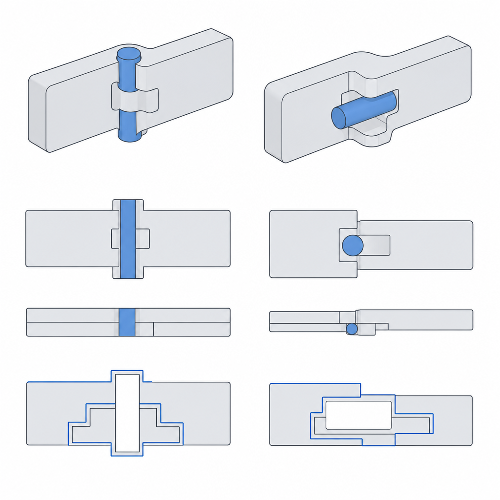
That description — the housing wrapping around the shaft as it rises — is the horizontal-axis case, laid down flat on the bed. With a vertical axis the mechanism is different: pin and housing grow as two concentric rings the whole height, and what traps the shaft are the flanges or lips at the ends, not a progressive wrap. Later you'll see that orientation changes a good deal more than this; for now it's enough to know that capture can come from wrapping the shaft from above or from closing it off with a lip, but in both cases it rests on the same air gap.
What makes it work is exactly what, in any other joint, would be a defect. A printed hole comes out narrower than its nominal size, and a shaft comes out fatter than its nominal size — the beads bite into the gap from both sides, as Tolerances for moving parts explains in detail — so the real gap is always smaller than the one you drew. In a sliding fit that's a problem to correct; here it's the margin you have to budget so that, after the printer eats its share, there's still air left between the walls.
One number, with a step in it
This joint lives or dies on a single value, and that value has a step in it. The radial clearance between the pin wall and the housing wall has a floor: below a certain threshold the two walls are so close that the beads weld as they're deposited and the part comes out solid, useless. That threshold is on the order of half a bead width — on a desktop FDM machine with a 0.4 mm nozzle, around 0.1–0.2 mm — and the clearance you actually want to design for sits above it, typically 0.2–0.4 mm. Below the floor there's no rotation possible; well above it, the pin wobbles. In between there's a real band, not a single point.
The reason for the step is the effective extrusion width. Your nozzle doesn't lay down an infinitely thin line: it puts down a bead about 0.4–0.45 mm wide, and if the air you left between the walls is on the order of that width or less, the material from one pass spills onto the next and the two weld together. That's why the threshold isn't universal: it depends on your bead, your flow, your temperature. An over-extruded first layer — exactly where the most material gets pushed out to the sides — can close the gap in the first few tenths of height even if the rest of the joint had plenty of clearance, leaving you with a pin welded only at the base.
The threshold is real, but it's not a perfectly sharp edge. Right at the edge you'll find in-between parts: pins that turn only under high torque, that give way after breaking a few welded spots in the first layer, or that come free in fits and starts. In fact, plenty of well-designed print-in-place parts come out slightly stuck and need a first forced turn to break free; that initial "crack" is expected, not a failure. Only when the gap drops well below the threshold is the fusion complete, and no rotation is left to break.
Once you're past the floor, the other end fails too: overshoot on clearance and the pin goes in, but it wobbles. Too much air leaves the shaft loose inside its housing, with a play you feel as a wobble that, on a long link, is amplified at the tip. The useful range is narrow: just enough above the welding threshold to guarantee it never fuses, without so much overshoot that the contact turns into a rattle.
Pin-axis orientation sets the contact surface
How you lay the part on the bed completely changes the contact surface you get — and the trade-off is unavoidable.
If you print with the pin axis vertical, perpendicular to the bed, each layer traces the circular outline of the shaft and the hole, and the surface of revolution comes out round and clean: the rotation is smooth because the contact is a true cylinder. The price is paid by the lip that closes the housing on top — the collar that wraps around the pin to trap it — which becomes a horizontal annular overhang and tends to collapse.
If you print it with the axis horizontal, parallel to the bed, you spare yourself that annular overhang, but you pay in the contact surface: the cylinder is no longer traced as a continuous circle on each layer, but as a stack of flat layers, and the stair-stepping leaves the contact faceted. Note, not around the whole perimeter: the top and bottom lines of the cylinder are the ones that stair-step, while the side flanks still come out smooth. The rotation is no longer against a perfect cylinder, and it shows as a catch in those two regions. In practice, this is usually the orientation chosen, because the lip overhang is a more serious problem than a somewhat faceted rotation, and you accept the faceting as the lesser evil. It's the same logic that governs any printed mechanism and that Layer orientation for motion develops: the direction of the layers decides which way the quality goes and which way the weakness goes, and you decide which defect you prefer.
Closing the trap without welding it: the closure overhang
Whatever the orientation, there's one part of the housing that almost always ends up hanging in the air: the closure that reaches over the pin to trap it. That closure begins above the air gap surrounding the shaft, so it has no material beneath it to rest on, and you can't put a support under it either: any support that touched the pin would weld the very joint you wanted to leave free — exactly the failure you're trying to avoid.
The way out is geometric, but the remedy depends on the orientation, because the overhang isn't the same in each case.
With the horizontal axis, you see the hole in profile, and its top is a bridge: an arc whose crown is nearly horizontal, and it droops. Here the classic solution is the teardrop profile: instead of closing the hole with a semicircular arc, you finish it in a point at the top, so each layer overhangs only a little more than the one below it. As long as that incremental overhang stays below the angle your printer can bridge without drooping — as a general rule in FDM, around 45° from vertical — the bridge prints self-supporting, with no support and without touching the pin.
With the vertical axis, there's no arc to point: the closure is that horizontal collar wrapping the shaft, and a teardrop in the plane of the section buys you nothing. What you tame there is the annular overhang, opening it up with a conical chamfer instead of a flat roof, so that the lip grows inward in small steps below the limit angle, rather than appearing all at once as a horizontal ledge.
In both cases the principle is the same: limiting how much each layer overhangs the one below is what lets you close the trap without contaminating the joint. If the closure droops, the fallen strands touch the shaft and weld it locally: you're back to the solid block, this time from the top instead of the base.
Material, and when to use it
The threshold doesn't just depend on the machine; the filament shifts it sharply. PETG tends to weld and stick far more than PLA — its bead flows and bonds readily to the one beside it — so with PETG you should head to the high end of the clearance range. PLA is more predictable and forgives a tighter margin. TPU, being elastic, forgives almost any clearance because it gives way at the first nudge, but its flexibility makes it a poor candidate for a pivot that has to hold a rigid shaft. If you're trying a new material-and-machine combination, recalibrate the floor: the one for your PLA doesn't carry over to your PETG.
There are a couple more levers for avoiding fusion at the base. Raise the pin a few tenths above the print plane on a small base of its own, so the joint isn't born in the over-extruded first layer; lower the first-layer flow; and watch for elephant-foot compensation, which widens exactly the base where you want it least. Any of the three keeps the gap open where the printer is most likely to close it.
The print-in-place pivot shines when later assembly would be a nuisance or outright impossible: articulated toys that have to come out moving, demonstration mechanisms delivered ready to go, chains of links where assembling an axle per joint would multiply the work by every articulation. You trade some rotation quality for skipping the entire assembly, and when there are many identical joints that trade pays off. It doesn't pay off on a joint that genuinely carries load, or that demands a fine, play-free rotation: there, a metal pin in a well-toleranced hole wins every time.
There are three failure modes, and all three follow from what's above. The first is accidental fusion: clearance below the threshold, or an over-extruded first layer that closes the gap at the base, and the part comes out solid. The second is excessive play: too much clearance and the pin wobbles, with a loose rotation that, on a long link, is amplified at the tip. The third is wear from the layer stair-stepping on the contact surface, especially with the horizontal axis: the facets rub and the rotation feels rough. With cycles, that break-in can improve the fit by burnishing the ridges, or worsen it by freeing debris that leaves more play; which of the two happens depends on the torque and the material. None of these is bad luck; all three come from choosing that one number wrong.
Before you print the first one, calibrate your welding threshold with the tolerance tower described in Tolerances for moving parts: that number, applied to the gap between pin and housing, is the difference between a part that's born spinning and a block that's born dead.