Embedded hardware: magnets, bearings, and inserts
Printed plastic has three weaknesses that no amount of clever design will fix: it holds threads poorly, it wears quickly under friction, and it generates no magnetic field. The serious way to build a mechanism that lasts is not to fight those weaknesses but to design around them. You embed a bought metal part that does know how to hold a thread, spin, or grip, and the plastic keeps what it's good at: holding shape and position. Inserts, nuts, magnets, bearings, and shafts turn a printed housing into something that screws together, spins, and latches like a finished product. The whole craft comes down to one thing: the pocket that captures that piece of hardware.
Two ways to capture hardware, and the load decides which
Every embedded pocket is one of two strategies, and you choose between them with a single question: will the part carry load, or does it just need to sit there?
If it carries load — a bearing supporting a shaft, an insert taking the torque of a screw, a magnet pulling a lid shut a hundred times a day — you want a press fit: the pocket is slightly smaller than the hardware and grips it by interference. No glue, no play, and the part doesn't shift a hair under working load. It's the same reasoning as the interference fit in Choosing the fit: clearance, transition, interference, except here the part you force in is hard, unforgiving metal: overdo the squeeze and what breaks is the plastic.
If it doesn't carry load — a decorative magnet, a part that only marks position — a drop fit plus adhesive is plenty: the pocket leaves a few tenths of a millimeter of clearance so the hardware drops in effortlessly, and a drop of cyanoacrylate fixes it. It tolerates your printer's drift better and cracks nothing, but it relies on the glue, so don't use it anywhere a force is tearing the part out.
Heat-set inserts: the reusable metal thread
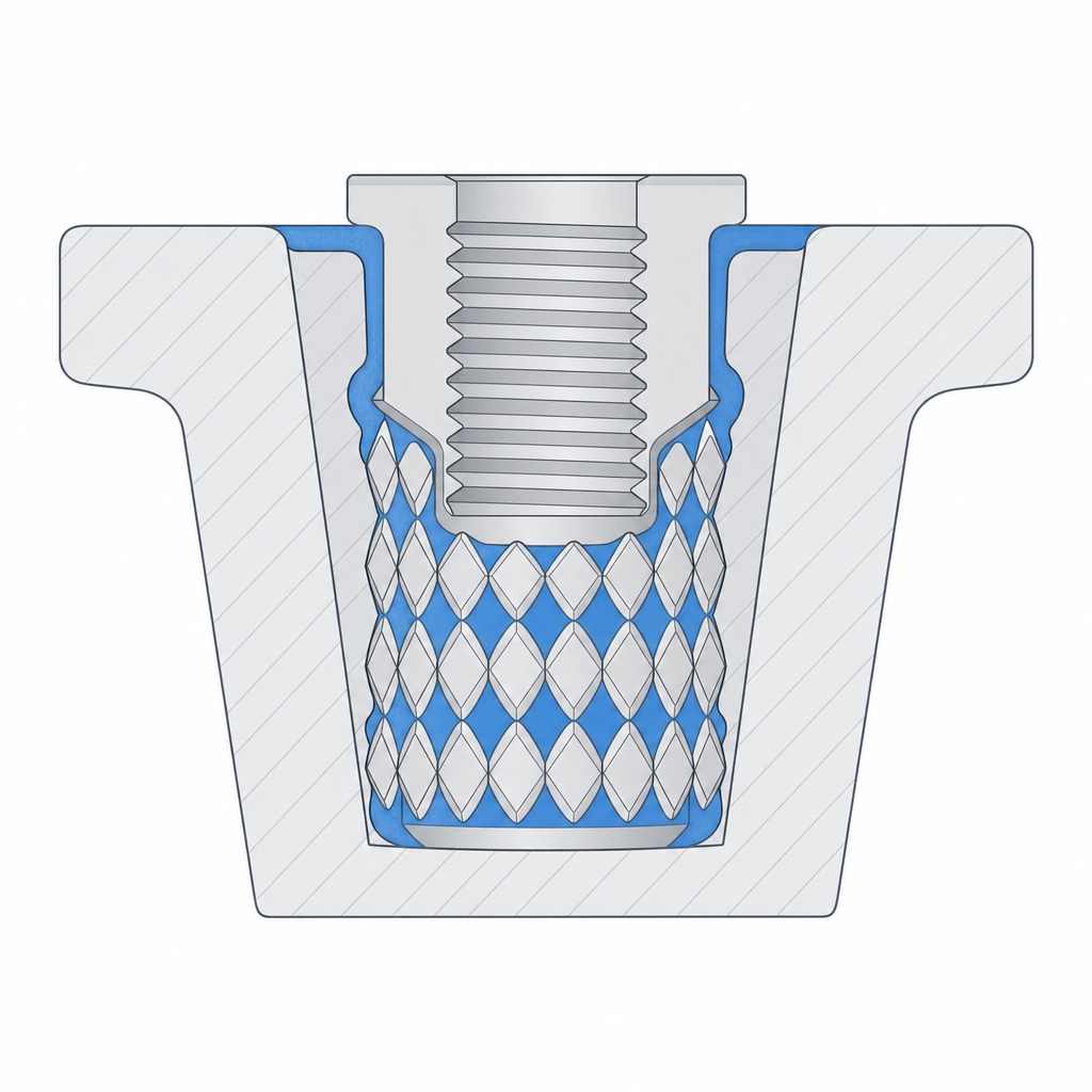
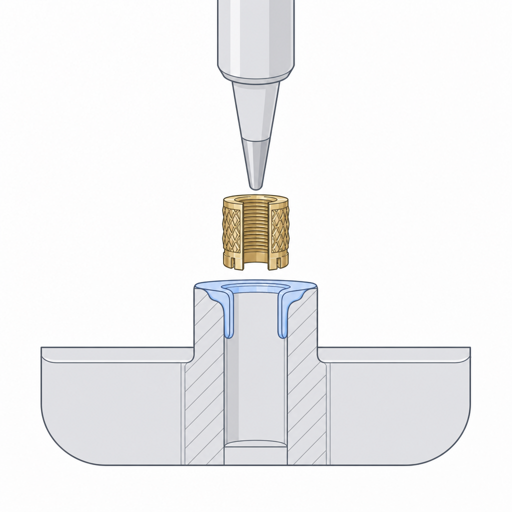
The most common load case is a thread. A heat-set insert is a brass bushing with a knurled exterior that melts into a hole slightly narrower than itself: the soldering-iron tip heats it — on the order of 220–250 °C for PLA, well above its softening temperature — and the plastic melts and flows into the knurling. On cooling you're left with a metal thread that survives hundreds of assemblies instead of stripping out the way a thread printed directly into the plastic does. It's exactly an interference fit, but made with heat instead of brute force.
The detail of bosses, wall, and pilot-hole dimension is in Designing for heat-set inserts; here it's enough to know that it shares the same principle as the other pockets: a printed cavity made to the exact size of a standard part.
Magnets: polarity before glue
A neodymium magnet in a pocket gives you snap-on, snap-off closures with no latches or springs. But magnets have a failure mode the plastic doesn't: the wrong orientation silently ruins the part. Glue in two magnets that repel, and the lid bounces instead of closing. By the time you notice, the cyanoacrylate has already cured in the pocket. Mark the face of each magnet with a marker before you assemble anything, physically bring the two mating magnets together to see which faces attract, and only then decide which face goes to the bottom of each pocket.
The pocket is blind — closed by a thin layer of plastic underneath — for two reasons. Aesthetics: the magnet doesn't peek out the outer face. And manufacturing: that closed face is a ceiling the printer has to bridge, so the pocket needs no supports. A closing wall of 0.6–0.8 mm — three or four top layers — is enough to hide the magnet without killing much of the closing force; with less, the bridge comes out sagging and pocked with holes.
Don't actually press it in: neodymium is sintered and brittle, and its nickel coating chips or flakes under the pressure. In practice magnets almost always go with clearance plus adhesive, not a press fit. And since the surface to glue is smooth nickel — a poor base for cyanoacrylate — it helps to use an activator, or epoxy, and to leave a vent groove at the bottom of the blind pocket so air and excess glue can escape; in a fully closed cavity the cyanoacrylate, which cures by moisture, is slow to grab or doesn't grab at all.
Respect, too, a physical limit that appears on no dimension: heat demagnetizes. A standard neodymium (N35–N52 with no high-temperature suffix) has a maximum service temperature around 80 °C, and above it loses magnetization irreversibly. That puts the heated bed (60 °C) uncomfortably close to that limit and, above all, pause-embedding near the hot end or gluing next to a freshly melted insert. Glue the magnets last, away from the soldering iron.
Bearings: interference in hundredths, and a wall that won't crack
When a printed bushing is no longer enough — because of high rpm, radial load, or a need for play-free rotation — you seat a standard bearing. The 608 (8 mm shaft, 22 mm outer diameter, 7 mm wide) is the workhorse, but the reasoning carries over just as well to a 623 or a 688.
The seat is designed as a press fit, with interference on the order of hundredths to a scant tenth of a millimeter, never microns. Remember that in FDM your real tolerance band is around ±0.1–0.2 mm — and XY usually comes out better than Z: the few-micron interference that secures a bearing in a machined aluminum housing vanishes into your printer's noise and leaves you a loose seat. Design the housing hole between 0.0 and 0.10 mm below the bearing's outer diameter; with that, plus the elasticity the plastic itself already provides, you push it in by hand or with a light tap. Going past that doesn't grip any better — it just cracks the wall.
Here the plastic's own failure mode shows up: the steel outer ring won't yield, so your wall does. If the wall around the seat is thin, the interference spreads and cracks it along the layers — which is exactly where an FDM part separates first. Leave plenty of material around it, comparable to the wall thickness of the bearing itself, so the seat grips it without bursting. The detail of how to size that wall is in Interference without cracking. A shoulder at the bottom of the housing sets the bearing's depth so you don't have to tune the interference to stop it.
| Dimension | Starting value | Why |
|---|---|---|
| 608 outer diameter | 22.0 mm | bearing nominal |
| Housing diameter | 21.90–22.00 mm | 0.0–0.10 mm interference; goes in by hand |
| Wall around the seat | ≥ 3 mm | spreads the stress, avoids cracking between layers |
| Stop shoulder | 0.8–1.0 mm of protrusion | fixes the depth without extra pressure |
Embedding by pause: enclosing the hardware inside the part
FDM allows a move that machining doesn't: pausing the print mid-height, dropping the hardware into its cavity, and resuming so the following layers enclose it completely. The finished part shows no opening at all; the nut or magnet is trapped inside the solid, impossible to remove without breaking it.
You model a pocket the size of the hardware and tell the slicer to insert a pause at the layer just above the pocket's top edge. The printer reaches it, stops, and retracts the head; you set the nut or magnet in place — polarity checked if it's a magnet — and resume. The next layer prints over the plastic and the hardware at once, closing it inside.
It works especially well for nuts that have to sit embedded in the middle of a wall, where there's no side to slide them in from afterward. If instead the nut can enter through an accessible edge, a normal side pocket usually suffices, like the one in Captive nuts and clearance holes. Three things to watch with the pause, and two are structural:
- The hardware must not stick up above the plane of the resume layer. If a nut peeks above, the head strikes it and drags it on resume — it's the number-one mistake in embedding by pause, and it usually ends with the part ripped off the bed. Leave it flush or below the next layer, with a minimal clearance so it seats properly.
- The pause cools the layer-to-layer bond. On a long pause, the last layer before stopping drops below welding temperature, and the layer that arrives after welds poorly against it: you're left with a delamination plane right where the hardware is. Minimize the pause time, keep the bed hot, and don't let the part cool down completely.
- Don't pause over a visible surface, because the pause seam almost always leaves a mark on the layer.
The pocket ceiling is a bridge, and wide bridges sag
Any pocket closed at the top — the blind floor of a magnet, the top face of an embedded nut, the clearance hole of a screw crossing a cavity — forces the printer to lay a bridge layer over the pocket's void. The nozzle crosses the gap with nothing beneath it, trusting the bead to pull taut between the two edges before it droops. If the pocket is narrow, the bridge comes out clean. If it's wide, the hot plastic sags in the middle and the ceiling comes out warped, with strings hanging or the opening closed up.
Design it with that crossing in mind. A short linear bridge is no problem: with good cooling, FDM crosses ten millimeters with room to spare, and tens of millimeters are possible by tuning speed and flow. What truly sags is a ceiling that's wide in two directions, where there's no nearby edge to tense from in any direction. If the pocket has to be wide like that, give the ceiling a small chamfer instead of a flat, abrupt step: a sloped transition gives each layer some material beneath it and turns an impossible bridge into a manageable overhang. And accept that the first layer over the void will always come out a bit worse than the rest; put it where it isn't seen and doesn't have to match a fine dimension.
Orient the pocket so the hardware enters straight
The last detail is orientation, and it decides whether your walls come out clean. A pocket whose walls are vertical — parallel to the print axis — is built by stacking beads one on top of another: smooth faces, a faithful dimension, the hardware enters straight and press-fits without resistance. A pocket whose walls end up as an overhang prints stepped, with each layer cantilevered over the one before; the faces come out rough, the dimension widens toward the bottom, and the press fit you designed for turns into a loose, inaccurate hole.
So orient the part so that the pocket's mouth faces up and its walls run vertical. That lines up three things at once: the walls come out clean, the blind floor becomes a short bridge instead of a deep overhang, and the crack you most worry about stays under control. Because a bearing's interference force is radial: it pushes the housing wall outward equally in every direction in the plane, no matter how you oriented the layers. What does matter is that this pressure tends to open the wall along the layer plane, by shear between layers. The orientation that gives the nice walls is almost always the same one that puts that weak plane where it does the least harm.
With the pocket well oriented and the ceiling solved as a bridge, the hardware is the easy part. For the two cases that recur most — the reusable thread and the captive screw — continue with Designing for heat-set inserts and Captive nuts and clearance holes, which turn these general rules into the concrete dimensions of each part.