Timing belt and pulley (GT2/HTD): backlash-free drive
When you need a motor in one place to drive a shaft in another, and every turn of the motor to translate into an exact turn of the shaft with nothing lost along the way, the timing belt is the answer. It's the system that moves the head of your 3D printer, and that's no accident: a toothed belt whose teeth mesh into a toothed pulley transmits rotation across a distance with no slip and no reversal play (backlash), which is exactly what any axis that has to position and repeat its position demands. The catch, when you print the pulley yourself in FDM, is that the tooth, the tiny feature everything depends on, is also the first to flake off, round over, or get skipped. This article is about why the timing belt positions so well, and how to print a pulley that holds up while meshing.
Why there's no play: the kinematics of meshing
The timing belt fools your intuition because it looks like a friction system, a band hugging a wheel, but it doesn't transmit by friction; it transmits by shape. The band is low-elongation: it carries a cord of fiberglass (or steel, where more stiffness is needed) embedded in the rubber precisely so it stretches as little as possible under load. Its teeth drop into the valleys of the pulley and bear against the flank of the next tooth, so the pulley advances tooth by tooth, counting them off. That's the difference from a flat belt, which does slip a little under torque and loses sync.
Out of that comes the transmission ratio, and it's exact: if the driving pulley has z teeth and the driven one z', the speed ratio is z'/z, without the slip that contaminates friction drives. There's no grip coefficient that depends on tension; there are teeth, and they get counted. That's why a timing belt doesn't accumulate error: it turns a thousand times and the position is still accurate to the tooth.
It's worth being precise about where that zero comes from. The timing belt does have a small inherent play between tooth and valley, specified by the manufacturer; the practical backlash is canceled because the belt is held taut, and the tension preloads the mesh in the direction of the load. With no tension there's play. Zero-backlash isn't an absolute geometric stop: it's what you get as long as the belt stays tight.
The tooth profile matters more than it seems. The old trapezoidal profile (the T2.5, T5, XL belts) has straight flanks, and it pays for that in two ways: the straight tooth interferes on the way into and out of mesh, and it concentrates the load at the tip of the flank instead of spreading it. The GT2 profile, 2 mm pitch, curved tooth, nearly semicircular, was designed to fix this: the curved flank bears over more of the tooth's surface and spreads the stress across the whole flank; the result is less vibration, less mesh interference, and less wear at a given size. HTD is the same rounded-tooth idea at larger pitches, for more torque.
What GT2 does not fix is the polygonal effect, or chordal action: because the belt wraps over an N-sided polygon rather than a perfect circle, the effective pitch rises and falls with each tooth that enters, and that introduces a small speed variation. That effect depends on the number of teeth in mesh, not on the profile, and exists just as much in GT2 as in trapezoidal; it's only attenuated by raising the tooth count on the pulley. For fine positioning, GT2 is the standard, and for good reason.
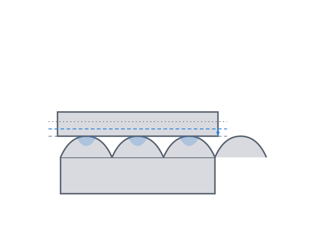
With the kinematics comes the dimension people most often get wrong. The belt meshes at the pulley's pitch diameter, not at its outside diameter. The pitch diameter is the circle where the belt's cord sits, and it's computed as: the pitch circumference is pitch × z, from which d = pitch·z/π. For a 20-tooth GT2, that's 2·20/π ≈ 12.73 mm of pitch diameter. The real outside diameter of the pulley, the tip of the teeth, ends up below that figure, but not because the valleys are recessed: it's because the belt's pitch line falls inside its cord, above the tips of the pulley's teeth. That offset is called the pitch line differential (PLD), and for GT2 it's ≈ 0.254 mm, so the outside diameter is OD = d − 2·PLD ≈ 12.22 mm for the GT2-20.
When the timing belt is the right choice
The timing belt shines in one very specific case: parallel shafts set apart by some distance, where you need repeatable positioning more than raw torque. It's the typical layout of a Cartesian motion system: motors fixed to the frame, a light moving mass, and the belt bridging the distance without the system losing steps. It's light, quiet, needs no lubrication, and tolerates the center distance far better than a gear train would, which would force you into a cascade of wheels to cover the same gap.
But it isn't universal, and it's worth knowing when to give way to something else. If what you're driving is high torque or you work in a dirty environment (dust, swarf, abrasives), a chain wins: its metal links take loads that would flake the teeth off a belt, and it isn't bothered by the grit that gets in between the rollers. If you need to transmit between shafts that aren't perfectly aligned and exact sync isn't required, a flat or round belt tolerates the misalignment and the controlled slip that the toothed belt won't allow. The toothed belt is the tool of precision, not of brute force, and not for dirty environments.
Printing the pulley: the tooth is the fragile part
This is where FDM starts breaking things, and almost always in the same place: the tooth. A pulley tooth is a small projection that takes the belt's load as a shear force at its base, and a printed projection is weakest exactly at the bond between layers. If you print the pulley lying down, with its axis of rotation parallel to the bed, the teeth come out stacked layer on layer in the direction of the load, and the belt flakes them off by delamination, lifting them like peeling back a flap.
The correct orientation is with the axis of rotation vertical, perpendicular to the bed, so the layers lie in the XY plane and each tooth prints as continuous layers running up its height. That way the shear the belt applies to the tooth runs along the beads and doesn't tend to peel layers apart. It's the same orientation logic that governs any part that carries motion load, worked out in Layer orientation for motion: put the weak plane where the force won't open it.
That orientation has a downside you can't ignore: with the axis vertical, the hub and the set-screw hole end up loaded in shear between layers, in the part's weakest plane, exactly the failure described in the note below. The orientation that saves the tooth is the bad one for the set-screw wall, and there's no single orientation that optimizes both. A metal insert is what fixes the hub, precisely because the geometry can't.
FDM adds a second problem. The curved profile of the GT2 tooth, and above all the bottom of the valley, where the belt seats, is a smooth curve that FDM only approximates with steps of the layer height: the stair-step effect. Those steps round and widen the actual valley relative to the one you drew, so a valley modeled to exact dimension comes out narrower and coarser than the belt expects, and the belt's tooth doesn't seat cleanly. The defense is to slightly oversize the clearance at the root of the tooth, give the valley a few extra tenths so the belt tooth enters without forcing despite the staircase. Exactly how much depends on your clearance calibration, the same one that governs any other printed fit, covered in Tolerances for moving parts.
And there's a limit worth keeping in mind: at 2 mm pitch the whole tooth is under a millimeter tall, and the bead width of a 0.4 mm nozzle is near the limit of what can resolve that profile. It isn't just the valley: the whole flank comes out approximate. For large, loaded printed pulleys a larger pitch, HTD-3M or 5M, usually does better, where the tooth is big enough that the stair-stepping matters less dimensionally.
One layout choice that saves trouble: a printed pulley performs much better as a driven wheel than as a driver. The driver is the one that puts torque into the system, the one that punishes the teeth most on every start; the driven one only takes it spread out. If in your mechanism one of the two can be metal, make the metal one the driver and leave the printed one on the driven side, where tooth wear advances far more slowly.
Tension, width, and wrap angle
A timing belt has to run taut, and the reason is kinematic, not frictional. Even though the mesh is by shape, a slack belt has play in the unloaded run, and the moment the system accelerates or reverses direction, that play lets the belt's tooth climb over the pulley's tooth instead of dropping into the valley: the belt skips a tooth. And skipping a tooth, in a system that positions by counting teeth, means losing the zero until the next homing cycle. That's why almost every setup carries a tensioner that keeps the run tight and removes that play.
Not every tensioner suits every job. For precision positioning, the case this whole article is about, you use a rigid tensioner: an adjustment screw that sets the center distance and won't let it float. A spring tensioner keeps the tension on its own, but it lets the center distance move under load, which degrades stiffness and repeatability; it's for transmitting power, not for fine positioning. If you're after precision, tension with a screw and lock it.
Tension is a balance, not a "more is better" affair. A belt that's too tight pulls on both pulley shafts with a constant radial force that loads the bearings, shortening their life, and, if the pulley is printed, can even deform the hub and throw the teeth off center, ruining the very precision you were after. The right tension is the minimum that prevents tooth skip under your system's maximum acceleration, and no more than that.
One geometric condition sets how much load the drive can carry: the wrap angle, the arc of pulley the belt wraps around. The load isn't carried by one tooth, it's shared by all the teeth in mesh at once. As a rule for torque capacity, manufacturers ask for at least six teeth meshing simultaneously to give full torque; note that's a torque criterion, not a "don't lose steps" one. In a typical Cartesian, with 16–20-tooth pulleys and a wrap of about 180°, eight or ten teeth mesh and you're well clear. The problem shows up with small pulleys and short wraps (when the tensioner or an idler pinches the path): you drop below that minimum, the load concentrates on two or three teeth, and under overload they wear and skip sooner. If the geometry leaves you short on wrap, raise the tooth count on the small pulley or rearrange the belt path.
And one manufacturing dimension the model usually forgets: the width. Common GT2 belts are 6 and 9 mm, and the pulley has to give the tooth that full width plus a margin. Above all, a printed pulley needs side flanges that keep the belt from walking off sideways; without them, the moment there's the slightest misalignment the band climbs the flank and walks off, and that's especially easy on a smooth idler.
| Parameter | Value / criterion | Why |
|---|---|---|
| Design dimension | Pitch d = pitch·z/π; outside OD = d − 2·PLD (PLD ≈ 0.254 mm) | The belt meshes at the pitch diameter, not the outside |
| Print orientation | Axis of rotation vertical (layers in XY) | The tooth works in shear along the beads, not between layers |
| Clearance at the valley | Nominal + a few extra tenths | Compensates for profile rounding from the stair-step effect |
| Width and flanges | Belt width (6/9 mm) + side flanges | Without flanges the belt walks off sideways |
| Teeth in mesh | ≥ 6 for full torque (wrap angle) | Spreads the load; with fewer, two or three teeth get overloaded |
| Fixing to the shaft | Bushing / metal insert for the set screw | A bare printed hub splits open under torque |
| Driver/driven split | Printed preferably as driven | The driver punishes the tooth more and wears sooner |
The three typical failures, one by one
A printed pulley fails in three recognizable ways, and each points to a distinct cause you can correct. The first is tooth wear and flaking from delamination: the teeth round over, lose flank, and end up chipping off in flakes between layers. If you see it, it's almost always orientation (you printed it with the axis lying down and the shear is opening layers) or a material too brittle for the belt's constant rubbing.
The second is the hub splitting open at the set-screw thread: the pulley meshes fine but slips on the shaft because the set screw has cracked the printed wall, or its seat has widened under torque until it loses grip. It's the failure of the bare hub with no bushing, and it's corrected in the fixing, not the tooth.
The third is tooth skip, and it has two origins worth distinguishing. One is insufficient tension, which leaves play for the belt to climb over the tooth when it accelerates; you fix it by tensioning. The other is a pulley with too few teeth. Every belt has a minimum pulley tooth count below which it shouldn't run: in GT2 the practical one is around 20 teeth, and you shouldn't go below 16 except with a toothed pulley (never with a smooth idler, which asks for more). Below that minimum two bad things happen at once: the cord flexes excessively and suffers fatigue, and the wrap leaves so few teeth in mesh that the load concentrates and the belt skips. The fix isn't to tension harder, which only loads the bearing, but to raise the tooth count on the small pulley.
Material: PETG or nylon over PLA, with caveats
A pulley tooth survives by sliding contact, and PLA, rigid and easy to print, is the worst candidate for something that wears: it's brittle and not very tough, so its teeth chip sooner. PETG and, better still, nylon give far more wear resistance and tolerate the belt's sustained abrasion without flaking. But neither comes without cost. Nylon is hygroscopic: undried it prints badly and loses properties, and it's also not very rigid, so on a precision pulley its tooth can deform under load and reintroduce play. PETG is tough but creeps under the sustained load of the set screw in the hub. And PLA, brittle for the tooth, is in return rigid and dimensionally stable: for a low-load driven pulley it can be perfectly fine. The PLA < PETG < nylon hierarchy holds for wear; the real choice also weighs stiffness, creep, and moisture.
And if the torque you're transmitting matters, don't ask plastic to do what plastic can't: embed a metal core in the hub, a turned bushing that takes the shaft and the set screw, and let the plastic do only what it does well, the teeth and the body of the pulley. How to house that metal hardware in the printed part without it working loose or sinking is in Embedded hardware: magnets, bearings, and inserts; it's the difference between a decorative pulley and one that moves load for months without splitting open.