Snap-fits that won't release
A snap-fit is the joint that asks for no screws: a tab that flexes during assembly and springs back to catch. Most are designed to open again — a lid, a battery compartment. But sometimes you want the opposite: it goes in with a click and never comes out again, not even by prying with a screwdriver. That permanent fit isn't a stronger snap; it's a snap with a different geometry and a far tighter safety margin. Everything is decided in a few tenths of a millimeter of hook, in a root fillet radius almost nobody models, and in an assembly clearance almost nobody calculates.
Two ways to store the elasticity
Every snap-fit works the same way: one part deforms elastically during assembly, clears an obstacle, and recovers its shape, trapped in place. What changes is what deforms, and there are two families.
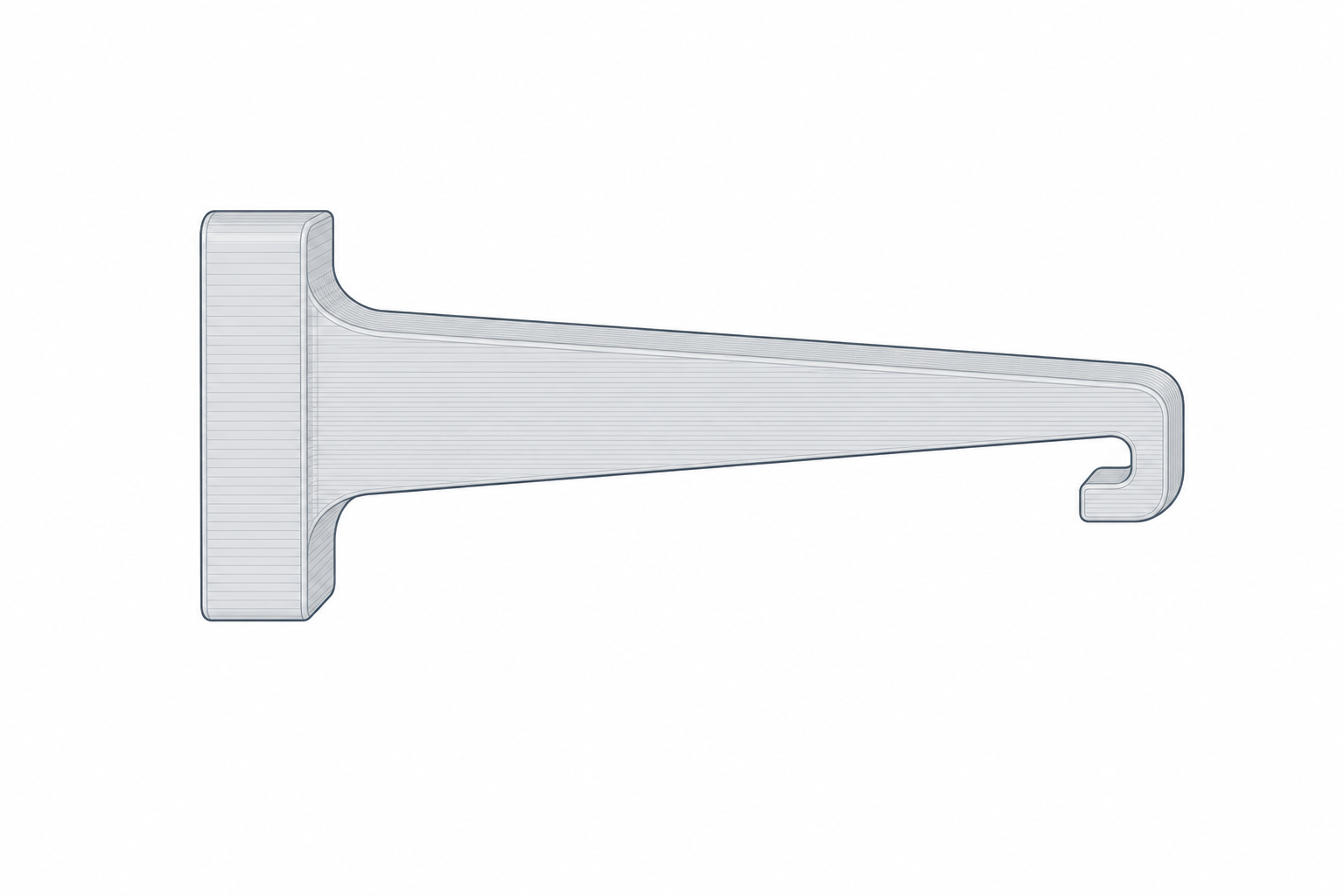
The cantilever is an arm projecting from the part with a hook at its tip. During assembly, the hook's ramp pushes the arm, the arm bends in flexure, the hook clears the ledge, and the arm springs back. All of the deformation concentrates in a single arm, which makes it easy to calculate — and just as easy to overload.
The annular snap is a lip running around an entire round profile — a shaft entering a hole, a cap over a jar — that seats into a groove. Here no arm flexes: the whole ring expands or contracts. Because the deformation is spread over the full perimeter, each point of the material works only a little, which is why an annular snap tolerates larger overlaps without breaking. If the part is already cylindrical, this is usually the more robust choice — with one orientation caveat you'll see below.
The retention angle: releasable or permanent
A hook has two faces, and they are two separate decisions. The insertion face is the ramp the arm climbs during assembly; its slope sets the assembly force. The retention face is the return face, the one that resists when you try to pull the parts apart, and it's what determines whether the joint is releasable or permanent.
If the retention face has a gentle ramp — say 30° or 45° relative to the pull-out direction — pulling turns it into a wedge: the axial force resolves into components and pushes the arm to flex again, the hook backs itself out, and the joint opens. That's a releasable snap, perfect for anything you'll want to open again.
For a permanent fit you do the opposite: you bring the retention face nearly perpendicular to the pull-out and strip away any exit ramp. Now pulling generates very little component that would flex the arm; almost all of the force goes straight into the arm root in bending and into the base of the hook. The part breaks before it releases. That's exactly what you're after.
The nuance matters: a face truly at 90°, or with negative interference, can be impossible to assemble without the arm exceeding its limit, because to go in the hook has to move aside by exactly as much as it would to come out. In practice a permanent fit is modeled around 80°–88°, not a true 90°: just enough that there's no exit wedge, but without turning assembly into a guaranteed fracture.
| Retention angle | Behavior on pull-out | Use |
|---|---|---|
| 25°–45° | Wedge: the arm re-flexes and releases | Lids, access panels, reversible assembly |
| 45°–80° | Hard to open, possible with a tool | Semi-permanent |
| 80°–88° (no exit ramp) | Won't release: breaks before it comes out | Sealed enclosures, tamper-proof |
The arm root: this is where everything is decided
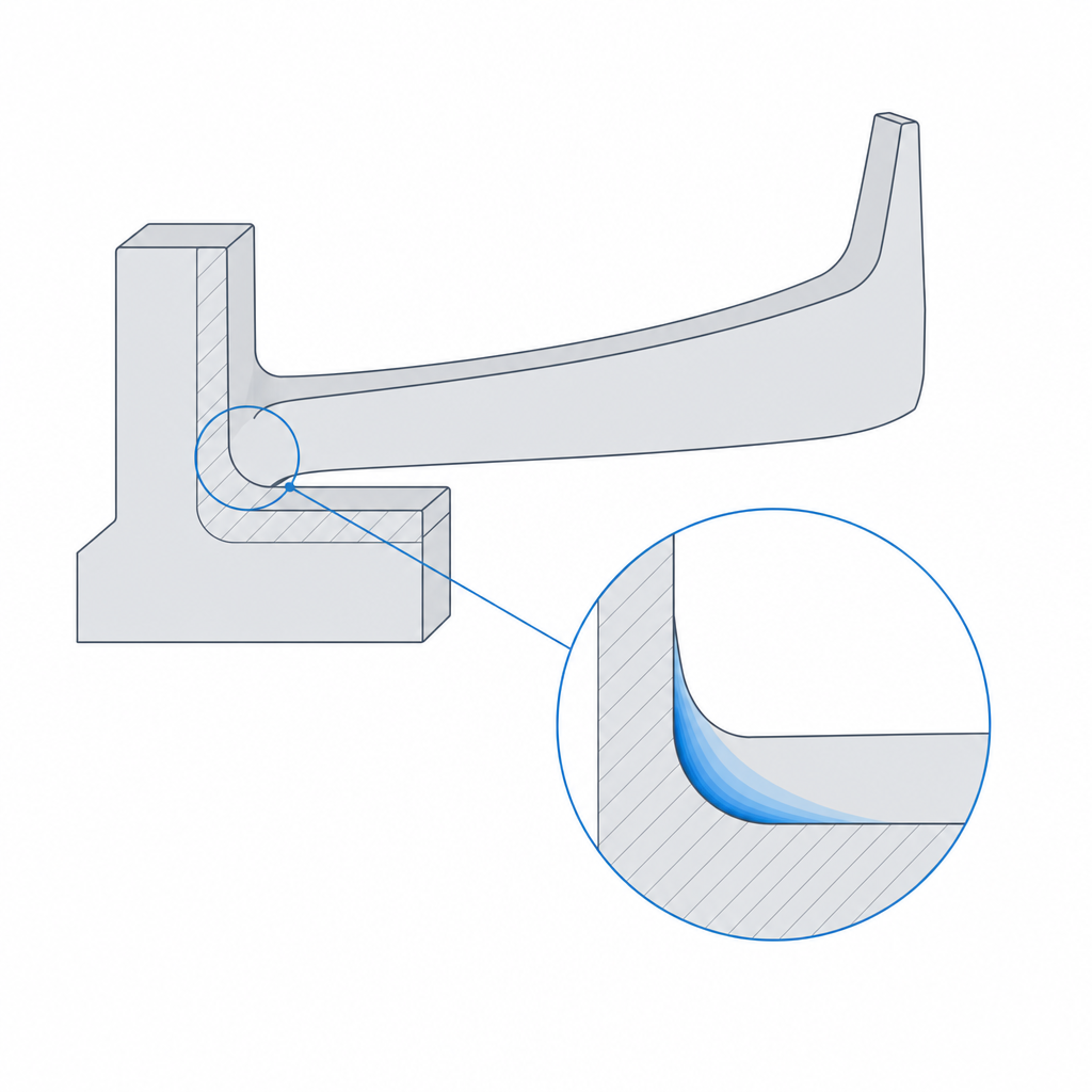
The most expensive mistake is to assume a permanent snap must be sturdy, and to make the arm short and thick. It's exactly the reverse. What kills a cantilever isn't the in-service load: it's the strain at the root during the single instant of assembly, when the hook climbs its ramp and the arm is bent to its maximum.
The physics is cantilever beam bending. For a given tip deflection (how far the hook must move aside — that is, its overhang), the maximum strain appears in the outer fiber at the root: it grows linearly with the thickness of the arm and falls with the square of its length. And that asymmetry is the practical key: lengthening the arm pays off twice as much as thinning it. Doubling the length divides the strain by four; halving the thickness divides it only by two. If your tab snaps on the first click, it's almost never that it's "too weak"; it's that it's too short — or too thick — for the overhang you're asking it to clear.
The material sets the ceiling, and it's worth not confusing two figures. The elongation at break of PLA in tension is around 2–6%, but that isn't the strain you can use: the allowable design strain is taken well below the break value. For a single-assembly snap it's usually taken at roughly half the elongation at break; for one that assembles and disassembles many times, considerably less. Working at the break limit is betting that the particular bead climbing the ramp has not the slightest flaw. PETG, and nylon above all, stretch a good deal more before breaking, so they tolerate shorter arms or larger overhangs at the same margin. The material weighs as much as the geometry: a tight cantilever that survives in PETG can snap outright in PLA.
Print it in the plane of the layers, not on edge
So far this is all classical strength of materials, valid for any process. FDM adds a trap of its own: the part is anisotropic, strong along the beads and weak between layers, where it's held only by the adhesion of one layer to the next (developed in Layer orientation for motion).
That decides the print orientation of any snap-fit. If you print a cantilever on edge — with the layers stacked in the same direction the arm is going to bend — each flex pulls directly on the bond between layers. The outer fiber at the root, right where stress is highest, coincides with the weakest plane of the part. The arm doesn't break by bending of the material: it delaminates, splitting open between two layers like a clean crack, often on the first assembly.
The rule is to orient the arm so it flexes in the plane of the layers, so that bending follows the beads along their full length and doesn't peel the bond between them. Lay it flat on the bed whenever you can.
Sometimes you can't: the assembly geometry fixes the flex direction perpendicular to the bed and the arm has to be printed on edge by necessity. When that happens, first consider redesigning to an annular snap, which spreads the stress and usually tolerates a compromised orientation better. If that isn't possible either, reinforce the interlayer adhesion exactly where it matters most: raise the extrusion temperature a few degrees, slow down at the root, and consider a wider or taller bead in that area to thicken the weld between layers. It doesn't match a flat-laid arm, but it's the difference between delaminating on the third assembly or the thirtieth.
Size the hook for a sensible assembly force
That leaves the piece most often neglected: how much overhang to give the hook. The overhang — how far the hook protrudes from the arm — is at once what holds the joint and what sets how far the arm has to flex to assemble it. You can't maximize retention without paying for it in strain.
A large overhang retains beautifully, but it forces the arm to move aside a lot, and you already know where that leads: past the strain limit at the root, and cracking. A tiny overhang assembles smoothly but barely catches and works itself loose. The balance for a permanent joint is to give just enough overhang for a full, reliable retention face, and then lengthen or thin the arm until the strain of that travel sits comfortably below the material limit. The insertion face, on the other hand, you do want with a gentle ramp: a shallow entry ramp (on the order of 30°) spreads the insertion force out along the push instead of demanding a sharp shove, and that's what turns assembly into a firm click rather than a crunch.
And then there's clearance, which in FDM is not a detail but half the job. A retention window modeled at nominal dimensions comes out narrower than you drew it: the extrusion width fattens the walls inward and elephant foot closes the first layers. Without a design clearance between hook and window — on the order of 0.1–0.3 mm depending on your printer and your calibration — the fit won't go in, or it goes in forced and bursts the arm during assembly, precisely the opposite of what you want. That clearance comes from the same calibration as any other fit; it's developed in Choosing the fit: clearance, transition, interference.
For a round part, the push button applies the same reasoning in ring form: the perimeter lip gives you spread-out, smooth retention without an exposed arm that can delaminate.
Deciding whether a particular snap should be permanent or releasable is, at bottom, the same question as Press-fits that hold: what the joint is for. If the answer is "it must never come apart," bring the retention face close to 90°, round the root, lay it down in the plane of the layers, give it its assembly clearance, and let the material — not a ramp — close the joint for good.