Jaw (spider) coupling: torque through elastic inserts
Two shafts that have to turn together are almost never perfectly aligned, and almost never start up smoothly. The motor yanks, the pump fights back with its inertia, and between them sit a few hundredths of a millimeter of misalignment that no real assembly ever removes. The jaw coupling solves both problems with a dumb part dropped in the middle: an elastomer star, the spider, trapped between the claws of two hubs that never quite touch. Torque doesn't pass metal to metal — here, plastic to plastic — but through rubber, which compresses, damps, and forgives. And that soft part, which looks like the accessory of the set, is exactly where it gets decided whether the coupling lasts or falls apart.
Torque travels through the elastomer, not the jaws
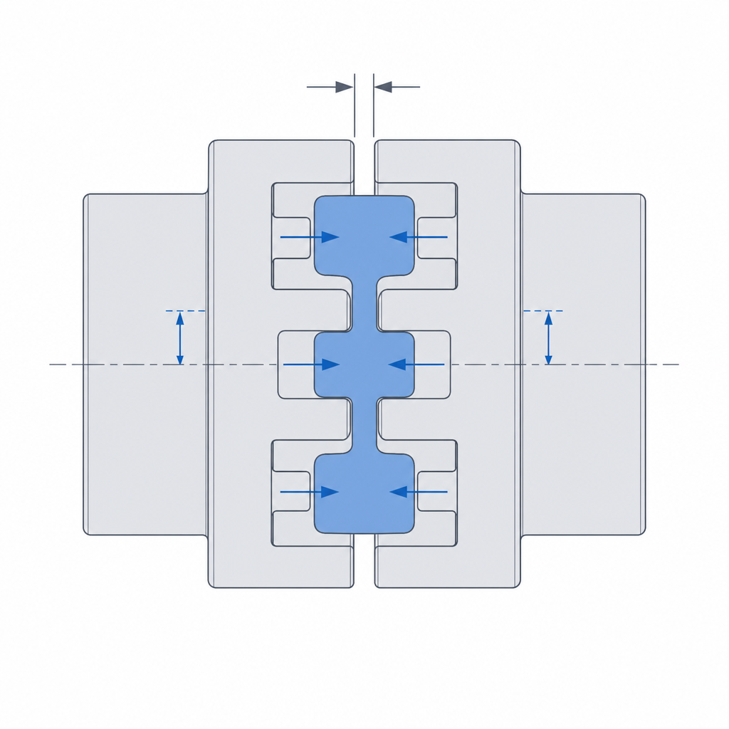
It's worth being clear that the jaws of one hub don't mesh with the jaws of the other. Assembled, they look like they do, but between a jaw of one hub and a jaw of the opposite hub there's always a spider lobe in the way. When the driving hub turns, its jaw pushes against a lobe, the lobe compresses, and on the far side of that same lobe the jaw of the driven hub takes the push. The force path is jaw → compressed rubber → jaw, never jaw against jaw. That interposition is the whole point of the mechanism.
Compressing the elastomer instead of slamming two solids together buys you three things at once. It damps torque spikes: an abrupt start or a load shock doesn't reach the other shaft intact, because the rubber absorbs the leading edge of the impulse by deforming before it transmits it. It tolerates misalignment in all three forms — angular (the shafts form a small angle), parallel (they run parallel but off-center), and axial (one slides a little along the axis) — each through a different route. And it filters torsional vibration: the fine torque pulsations, the ones that would make a rigid drive chatter, dissipate in the rubber's hysteresis. In exchange you pay a price worth knowing about.
The first two misalignments are absorbed by the lobes, which deform differently on each side to accommodate the geometric offset without binding. Axial is a different animal: it isn't absorbed by the rubber deforming, but by the gap you leave between the front faces of the two hubs. If you model that gap at zero, the hubs butt together the moment assembly nudges them a hair closer, and the coupling seizes before it turns. Same with radius: the tip of one hub's jaw must not touch the root of the other. These are two design clearances you have to draw by hand in FDM — an axial hub-to-hub gap and a radial jaw-to-root clearance — because the printer won't hand them to you.
What you pay: windup, and when this isn't your coupling
That same damping elastomer introduces torsional elasticity. When you apply torque, the lobe compresses before the driven shaft actually starts to move: there's a lag angle between input and output that grows with load. This is windup (the elastic wind-up of the coupling), and it means the angular position of the output shaft is not a rigid function of the input's. To drive a pump or run a fan it makes no difference at all. For a shaft that has to position — an encoder, a leadscrew, anything where the exact angle counts — windup is noise leaking into your loop.
That's why the selection rule is direct: choose a jaw coupling with a spider when what you're after is damping — abrupt starts, pulsating torque, mixed misalignment, motors and pumps that vibrate. If what you need is full torsional stiffness, this isn't your coupling. A rigid coupling transmits the angle with no lag but won't take a tenth of misalignment. An Oldham decouples parallel misalignment while keeping angular stiffness, at the cost of two sliders. The spider occupies the middle ground: tolerant and soft, never stiff. Demanding stiffness of it is asking it to stop being what it is.
Print the rigid rigid and the soft soft
Here FDM fits almost by design, because the mechanism is born bimaterial: two hard hubs and a soft spider. Print the hubs in PETG (or ABS/ASA if things run hot), which is where you want stiffness and shear resistance in the jaws, and the spider in flexible TPU, which is where you want elastic deformation. Avoid PLA except for low torque or a prototype: it's stiff but brittle, and precisely in the abrupt starts and torque spikes this coupling is meant to defend against, a PLA jaw shears from brittleness sooner than a PETG one. On top of that, the spider's internal friction generates heat in service, and PLA's Tg (55-60 °C) sits dangerously close. If your machine is multi-material you can print the whole thing in one go; if not, you print the spider separately as its own part and assemble it — it is, after all, the replaceable part of the system.
The TPU's Shore hardness is the tuning lever, not a detail of whichever spool you have on hand. A softer TPU damps more and tolerates more misalignment, but introduces more windup and takes less torque before it deforms excessively; a harder one transmits more clean torque and allows less lag, in exchange for filtering shocks less well. The useful range for the part to still be a spider runs from 95 A — the most common TPU, and a good starting point — up to about 50 D as a realistic ceiling. Past that you no longer have an elastomer: a 60 D barely damps and, in a thin FDM spider, behaves more like a rigid hub than an elastic insert.
Lobe preload sets the backlash
There's one parameter almost nobody models consciously, and it governs behavior at low torque and on reversal: how hard the jaws squeeze the spider at rest, before any load comes in. This is the lobe preload, and it has a narrow window.
If you model the spider with clearance between jaw and lobe, then on reversing direction the jaws travel that gap with nothing loading them before they push again: backlash appears (lost motion on reversal). The jaws clatter, make noise, and introduce a dead step on every reversal, and in a coupling that's supposed to be smooth that stands out especially. The fix is to model the spider with a slight squeeze, so that at rest the lobes are already lightly compressed against the two jaws flanking them: contact is never lost, there's no gap to travel, and reversal is continuous. But overdoing it has its own cost. Excess squeeze keeps the rubber permanently compressed, raises internal friction, generates heat in service, and accelerates lobe wear. The right preload is just enough that there's no play on reversal, and not a tenth more.
And count on FDM shifting that dimension before you ever measure it: the TPU spider comes out a touch thicker than nominal and the jaw gaps a touch tighter than drawn, so a fit modeled at zero is already born with printed squeeze. Budget the preload against what the part measures, not what you put on screen; the reasoning for why hole and shaft drift in opposite directions is in Tolerances for moving parts.
Keep the hub from slipping on the shaft
Everything above assumes torque reaches the hub from the shaft with no losses, and that's where the silent failure of any coupling lives: the hub slipping on a round shaft. A smooth cylindrical bore clamped onto a smooth shaft transmits torque only by friction, and the moment starting torque exceeds that friction, the hub turns on the shaft without dragging it along. You lose the drive without breaking anything, which is the worst case: hard to diagnose.
The fix is the same as in the rest of the couplings: break the rotational symmetry of the contact. A set screw that bites the shaft, a keyway that houses a key, or directly a non-round shaft — hexagonal, with a milled flat, D-shaped — that locks rotation by form. A non-round profile is the most reliable in plastic, because it bears on edges and doesn't depend on the friction of a screw that loosens with vibration. If you're going to insert a metal set screw or a nut, budget its pocket as embedded hardware; Embedded hardware: magnets, bearings, and inserts explains how to house them so they don't split the hub wall.
How much torque, at how many revs
Before the failure modes, an order of magnitude so you can size it. A desktop-sized FDM spider — hubs around 25-30 mm in diameter, a 95 A TPU spider with a decent wall — moves the torque of a NEMA 17 or NEMA 23 and that of small pumps and fans without drama: on the order of a few tenths up to a couple of N·m sustained, with margin for larger spikes, which is exactly what the rubber is there to soak up. The limit usually isn't the peak torque but hysteresis heat: the faster it spins and the more compression cycles it puts in per second, the more energy the TPU dissipates in its own deformation, and the closer it gets to softening. Above a few thousand RPM, or with pulsating torque at sustained high speed, the bottleneck stops being the lobes' strength and becomes their temperature. If your application lives there, raise the Shore hardness, scale the coupling up, or accept that the spider is a consumable and replace it on a schedule.
The failure modes and where to look
When a jaw coupling fails, it does so through one of four places, and all four can be seen coming.
The first and most common is the spider: under high or sustained torque, the lobe TPU is crushed and loses its shape, or tears at the contact zone with the jaw, which is where compression is highest. A crushed spider stops preloading and backlash reappears; a torn one stops transmitting. If your drive exceeds what the chosen TPU can give, raise the Shore hardness, or spread the torque over more contacts — more jaws and more lobes, or a larger-diameter coupling. What doesn't work is fattening one lobe in place: it lives in a fixed gap between two jaws, and enlarging it forces you to redesign the whole hub.
The second is sheared jaws: a jaw that's too thin, or printed with its axis in Z, won't take the torque moment and snaps at the base. It's a failure of section and orientation at once — give it more material and lay it down in XY, as we've already seen.
The third is slow and treacherous: growing backlash. The spider doesn't break all at once, but the TPU yields little by little under repeated compression (creep), loses preload, and the coupling that started out silent begins to clatter on reversal months later. It hasn't broken; the elastomer has relaxed. When it shows up, don't go looking for a crack: replace the spider — that's what the sacrificial part is for — and consider a harder TPU if the torque regime justifies it.
The fourth isn't in the coupling but in its grip on the shaft: the hub-to-shaft fixing working loose. A set screw that yields to vibration, or a friction fit that gives up to heat, leaves you a hub spinning free on its shaft with nothing broken. It's the same silent failure from before, returned with use: check the set screw's tightness, or move to a form-locked shaft if vibration is shaking it loose.
If what you have in hand isn't damping but fixing a hub to its shaft so it never slips even once, the problem stops being about the elastomer and becomes one of form fit: Tolerances for moving parts takes you from the clearance you draw to the clearance that comes off the printer.