Scotch yoke, quick-return, and special cams: the conversions crank-slider can't cover
The crank-slider is the workhorse for turning rotation into reciprocation, but it doesn't always give you what you need. Sometimes you want perfectly sinusoidal reciprocation, not the slightly skewed curve you get from a finite-length connecting rod. Sometimes you want the forward stroke to be slow and forceful and the return to be an unloaded snap. Other times you want to drive several pistons out of phase from a single rotary input. For each of those specific kinematic requirements there's a mechanism the crank-slider doesn't handle well, and they all share one Achilles' heel when you print them in FDM: they all depend on sliding contact, and sliding contact wears. It's worth understanding which motion law each one delivers before you choose, because the geometry that makes them special is the same geometry that makes them hard to print.
The Scotch yoke gives pure sinusoidal reciprocation
The Scotch yoke is the cleanest way to get simple harmonic motion. A pin mounted on the crank runs in a transverse slot — perpendicular to the output line — cut into a part that can only translate. As the crank turns, the pin slides freely up and down inside the slot while pushing the part side to side, bearing against the two faces of the channel. Those faces are what transmit motion in the output direction; the slot passes only that component and absorbs the other by allowing the pin to slide. The result, by construction, is the radius times the sine of the crank angle. Not an approximation: an exact sine.
That is what sets it apart from the crank-slider. In the crank-slider, the finite length of the connecting rod introduces a second-harmonic term that makes the displacement, velocity, and acceleration asymmetric between the forward and return strokes; the shorter the rod relative to the crank, the further the output departs from a sinusoid. The Scotch yoke has no connecting rod, so it has no such term: position is a perfect sine, velocity a perfect cosine, and acceleration a perfect sine, symmetric in both directions. That gives you a useful design corollary: the yoke's peak acceleration stays at r·ω², below the crank-slider's, whose second-harmonic term pushes its peak higher. Less peak acceleration means less inertial load. That's why it's the right mechanism when you genuinely want pure harmonic motion — vibrators, dosing pumps, test rigs where the motion law has to be clean — and it also comes out more compact, because you skip the connecting rod and its swept space.
The price is paid at the sliding interface. The pin doesn't roll inside the slot: it slides along the whole stroke, absorbing the transverse component through continuous friction against the two faces of the channel. That constant sliding, cycle after cycle, is wear concentrated on a narrow track. But in an FDM part the failure usually shows up in the pin before the slot: a small-diameter plastic pin works in bending and under line contact pressure against the wall, and it rounds off or yields before the slot ever opens up. So in a printed yoke, the realistic mitigation is to give the pin a generous diameter or, better, replace it with a metal pin or a metal sleeve that can take the contact. The clearance that starts out as clean sliding opens up anyway, and with it the rattle that ruins the very sinusoid the mechanism exists to produce.
Quick-return splits the time between working and returning
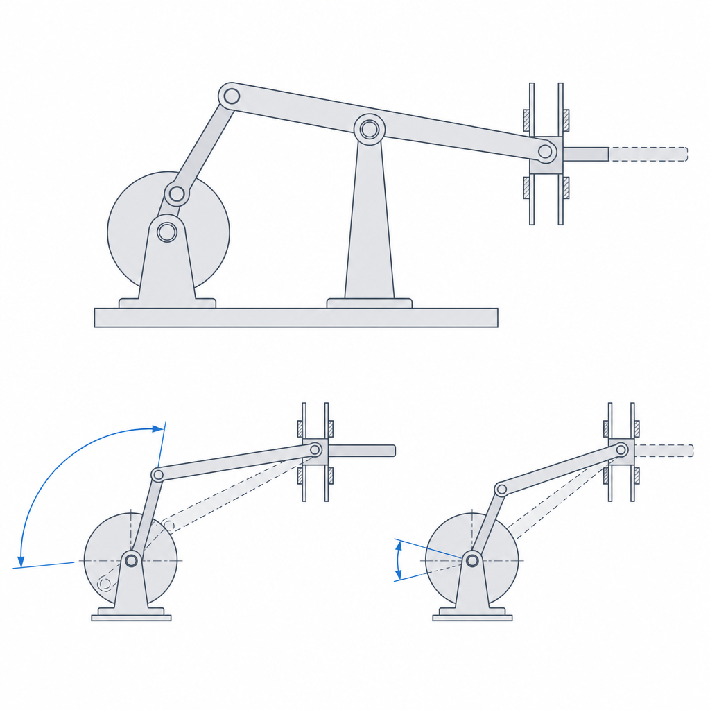
The quick-return mechanism — the heart of the shaper — solves a different requirement: that the tool spend more time on the working pass than on the way back. Two related mechanisms get lumped together too casually, and it's worth keeping them apart. The Whitworth version uses a crank that makes full turns and drags a slider along an arm that also rotates fully; the oscillating-lever version (crank-and-slotted-lever) uses a crank that drags a slider through the slot of an arm that only rocks from side to side, without going all the way around. The classic shaper almost always uses this second one, the oscillating type, and that's the one we'll describe. The kinematic idea, in both, is to break the symmetry. In a normal crank-slider, the crank sweeps the same amount of angle to push as to retract, so the forward and return strokes take the same time. Quick-return introduces a geometric asymmetry — the crank drags an oscillating arm pivoted at an offset point — so that the working stroke consumes a large fraction of the crank's turn, and the return stroke the small fraction that's left.
The result is that, at constant crank speed, the cutting pass advances slowly and the return pass moves quickly. And that slow pass is exactly the one that gives force at the tool: at the same power, lower linear speed means more force available at the edge. That instantaneous mechanical advantage comes from the velocity ratio, not from more torque at the motor. That's exactly what you want in a machine where only one direction does work: the edge removes material on the forward pass, unhurried and with force, and repositions for the next pass during the dead time, without wasting the cycle. You make better use of each turn of the motor because you don't ask it for the same speed when it's cutting as when it's just repositioning.
The trade-off here is less about wear than about forces. The asymmetry that gives you the slow pass concentrates unfavorable transmission angles at certain positions, where force is transmitted obliquely and loads the pivots instead of advancing the tool. In FDM that means well-sized pivots and controlled clearances: a pin with too much clearance at a poor-transmission-angle position shows up immediately as dead motion and lost thrust right when you're asking for the most force.
Grooved cams trap the follower in a channel
Face and drum cams solve the problem of programming an arbitrary motion without relying on a spring to keep the follower against the cam. In a conventional disc cam, the follower rests on the outer profile and needs a spring to push it against the cam at all times; if the acceleration on the way down exceeds what the spring can follow, the follower lifts off and the motion law is lost: cam jump. Grooved cams eliminate that dependency by capturing the follower inside a channel.
In a face cam, the groove is engraved in the flat face of the disc and the follower runs in it; as the disc turns, the walls of the groove push the follower in both directions, so closure is by form and no return spring is needed. In a drum cam, the groove is a helical or free-profile track cut into the cylindrical surface of a drum, and the captured follower moves parallel to the axis of rotation as the drum rotates. The latter is especially compact and clean when the output you need is axial — advancing something along the axis itself — because all the motion programming lives on the surface of the cylinder.
Form closure has its price, and it comes as two distinct seizing modes. The first is about clearance, and it's a fine balance: too much, and the follower rattles wall to wall on every reversal, eating into the precision of the motion law; too little, and the two walls trap it at once, denying it the play that sliding contact needs to avoid snagging. The second is independent of clearance: the pressure angle. Where the track profile is very steep, the follower pushes against the wall with a large component that tends to jam it, even when the clearance is correct. A grooved cam with a high pressure angle seizes by geometry, not by fit; the cure is to smooth the profile so the rise isn't so abrupt. A grooved cam forgives neither a miscalculated clearance nor an overly aggressive profile.
The swashplate splits one input into several out-of-phase outputs
The swashplate is the most striking conversion of the four: a disc inclined relative to the axis of rotation turns a single rotary input into the axial reciprocation of several followers distributed around the disc. Here too, two related mechanisms get confused by name, and they're worth separating. In the non-rotating plate (swashplate) — the one in the axial-piston pump and the helicopter rotor — the followers rotate around the axis and the inclined plate does not rotate with them: it imposes the stroke on them from a fixed or variable-tilt part. In the wobble plate the reverse happens: the plate rotates and wobbles, and the followers stay still, resting on its face. The kinematics we describe here — each fixed follower resting on the face of a plate that spins inclined — is the wobble plate; the helicopter swashplate reaches the same distribution by the opposite route, with the plate held still and the followers rotating. In both, because the plate is inclined, it presents each follower with a height that rises and falls sinusoidally through each revolution.
And because the followers are distributed angularly, each one reaches its high point at a different instant: the same rotation delivers the same reciprocation to all of them, but phase-shifted according to its position. Where the crank-slider gives you one output per crank, the plate gives you as many as the followers that fit on the disc, all governed by the same part and by a single tilt angle. Tilt the plate more and every stroke grows at once; the phase between them is fixed solely by their angular distribution.
The weak spot is, again, the contact point. Each follower slides on the face of the plate as it turns, just like the yoke's pin in its slot, and it wears for the same reason. If the follower is a simple shoe that rubs against the face, the wear is severe; that's why in serious versions each follower carries a roller or a low-friction shoe that rolls instead of dragging.
In FDM, it all turns on the track and the material
What ties these four mechanisms together is that their motion comes from a sliding surface — a slot, a track, an inclined face — and not from a pivot that only rotates. That changes the rules when you print them, and the first one is orientation, but with an important nuance. When the contact surface is flat, it pays to print it in the XY plane, where the beads run along the sliding direction rather than across it: a flat track printed on edge leaves layer steps transverse to the motion that the follower feels as roughness and that accelerate wear. That holds for the groove of a face cam or for a straight guide — it's the same logic as Layer orientation for motion applied to a track instead of a pivot. But it stops holding when the track isn't flat: in a drum cam the helical track wraps a cylinder, and in the plate the face is inclined, so no orientation keeps the contact surface from crossing layers. There it isn't orientation that rules but the material and the post-processing: sanding or smoothing the track does more for service life than fighting with the print angle.
The second lever is the sliding clearance, which has to be uniform along the whole stroke. Here just any clearance won't do: it's the same critical tenth of a millimeter that separates "slides" from "seizes," and you calculate it the same as any other moving fit, starting from the real gap your printer leaves and not the nominal one you drew, as Tolerances for moving parts details. A clearance that varies along the slot introduces tight zones and zones with play within the same stroke, and that wrecks the motion law in two ways at once.
The third is the material and the shape of the follower. Constant sliding contact punishes the track far more than a pivot that only turns, so PLA — stiff but with poor abrasion resistance — falls short. PETG holds up better under sustained rubbing, and nylon better still, but printed nylon absorbs moisture and swells, and that shifts the very clearance you just dialed in to the tenth: in a mechanism where the sliding fit is life or death, nylon only works if you dry it and, ideally, seal it. If you want dimensional stability and low friction at the same time, look toward a carbon-reinforced PA. The textbook material for sliding contact would be POM (Delrin), with extremely low friction, but almost nobody prints it in FDM because it adheres terribly to the bed, which is why it isn't a practical option. And where the geometry allows, replace the dragging shoe with a roller follower that rolls: trading sliding for rolling is the single biggest improvement you can make. Above all that, don't forget the cheapest fix of all: a printed sliding track wants grease. A PTFE or silicone grease compatible with plastics is the number-one wear mitigation and the one that costs the least to apply.
| Mechanism | What it gives you | Failure mode to watch |
|---|---|---|
| Scotch yoke | Exact sinusoidal reciprocation, no connecting rod, compact | Wear of the slot and, sooner, of the pin: make it metal |
| Quick-return (oscillating lever) | Slow, forceful forward; fast, unloaded return | Play in pivots and poor transmission angles |
| Face / drum cam | Programmed motion with form closure, no spring | Miscalculated clearance and high pressure angle |
| Swashplate | One rotation into several out-of-phase axial outputs | Wear of the face; use a roller, not a shoe |
When the output you need isn't reciprocation but intermittent rotation — advance a step and stop, over and over — you move to a completely different family of mechanisms: that's where the Geneva drive and ratchets come in, which are best treated separately because their problem isn't sliding but the shock of starting and stopping.