Magnetic closure: effortless, self-aligning joining
An embedded magnet is the most convenient closure you can print: two parts that seek each other out, meet with a soft click, and separate with a pull, with no tabs to delaminate, no threads to strip, not a trace of mechanical wear after a thousand cycles. But all that ease rests entirely on one number almost nobody bothers to pin down: the thickness of plastic wall left between the magnet and the mating face. That wall is invisible in the model, and it is the only thing that decides whether the closure grabs with authority or the two parts sit loose, held apart by a tenth too much.
The force lives in the air gap, and it collapses fast
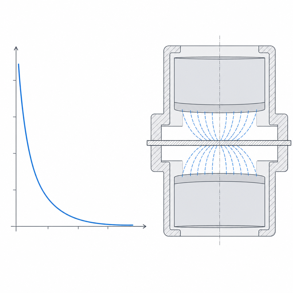
The first thing to accept is that the attraction between two magnets does not decay gently with distance: it caves in, and it caves in quickly. The air gap — the total space between the two facing pole faces — is not just the air between the two closed parts: it is the sum of the two plastic walls covering each magnet, plus whatever slack remains when the parts close. And the force-versus-air-gap curve is one of the punishing ones: the closer that separation gets to the magnet's own size, the steeper the fall.
A note on regime is worth making here, because it sets how much each tenth hurts. With small neodymium magnets (the 5–10 mm diameters you'll actually embed) and thin walls, you're working in the near field: the air gap is well under the magnet size, and in that range the force still changes a lot with every tenth, but it hasn't fully collapsed yet. The textbook collapse — force divided by eight when you double the distance — belongs to the far field, once the separation already exceeds the magnet. The practical consequence is the same in both cases and overrides every other rule: the dominant parameter is the wall thickness over the magnet, and you want it as thin as your printer can lay down reliably.
A 0.4 mm wall on each side puts 0.8 mm of plastic in the air gap before you even count clearances; going up to 0.8 mm per side does not add "a little" distance, it leaves the closing force at a fraction of what you had. That is why the magnet pocket is always designed blind against the mating face, with the minimum printable wall — on the order of a couple of beads, that is, two extrusion lines, 0.4–0.8 mm — and you never leave the magnet recessed "just in case." Every tenth you save on that wall comes back multiplied in grip.
It aligns itself, unless you flip the polarity
The second virtue of a magnetic closure, after the convenience, is that it self-aligns. Two magnets facing each other with the right polarity don't just attract head-on: as soon as they come together off-center, the field produces a lateral component that pushes them to meet face to face, because that is the position of minimum energy. The part drops into place on its own. That makes it an excellent assembly guide as well as a closure: a lid you set down blind and that seats itself centered without you looking.
You have two ways to build the pair, and the choice is between energetic alignment and tolerance to rotation. The magnet-to-magnet pair usually self-aligns more decisively, because both sides contribute field. The magnet-to-steel-plate pair — a magnet against an embedded disc or washer of mild steel — gives up some centering in exchange for being insensitive to orientation: the steel lets itself be attracted in any position, so the closing part can rotate freely without a flipped pole rejecting it. On force there's no universal rule: a thick, good-quality ferromagnetic plate concentrates the flux and can match or beat a second magnet of the same size, while a thin, poor plate falls short. And mind that the plate pays its own air gap too: it needs its own thin wall against the mating face, exactly like the magnet, so don't treat it as if it closed bare.
And here is the failure mode that doesn't forgive, because it's an assembly mistake and not a calculation one: polarity. If you glue the two magnets in without verifying that the facing faces attract, you have a fifty-percent chance of building a flipped pair that repels instead of closing. The closure isn't merely loose: it actively pushes the parts apart. The discipline is trivial and mandatory: before applying any adhesive, bring the two magnets together already in their parts, confirm that they seek each other, and mark the face or the direction on each one. A flipped pair discovered after gluing means tearing the magnet out and starting over.
Capturing the magnet: blind pocket or print pause
There are two clean ways to house the magnet, and they differ by whether the part can be reopened or is sealed for good.
The first is the blind pocket: you model a cylindrical recess with its mouth facing up, with its floor — the thin wall — on the side of the mating face, and you leave the mouth open to insert the magnet from behind once printed. The magnet goes in press-fit or glued, ends up captured behind the thin wall that faces the other side of the closure, and none of it shows through the face that touches. This is the default option: simple, no maneuvers in the slicer, and it leaves the magnet accessible if you ever want to replace it.
The second is the print pause: you program the slicer to stop the machine at exactly the height where the pocket is flush with the layer in progress, you insert the magnet by hand, you resume, and the following layers close the plastic over it, sealing it inside the part. The capture is permanent in translation — the magnet can't come out even if it lets go of the adhesive — and it saves you the glue entirely if the fit is good. Even so a tight fit is worth having: buried but loose, the magnet can rock or rotate inside the cavity, and a magnet that rocks moves its pole face nearer or farther and makes the closure erratic, or in a magnet-to-magnet pair turns far enough to lose alignment. And the pause has its manufacturing traps: get the polarity right before you close it, because afterwards there's no going back; reckon that a neodymium magnet near the steel nozzle or near a bed with a ferrous sheet can be attracted and shift on resume, ruining the insertion or colliding with the print head; and set the magnet slightly below the plane of the closing layer, because if it sticks up, the plastic meant to bridge over it sags and the capture fails.
In both cases the thin wall goes against the mating face for the reason from the first section: that is the side that pays the air gap. The pocket opens toward the inside of the part, never toward the face that closes.
Orient the part so the thin wall comes out clean
Deciding which side the thin wall goes on isn't enough; you also have to decide how it prints, because that wall is the most delicate point of the whole geometry. The ideal is to orient the part on the bed so that the mating face — and with it the thin wall — sits down, against the bed: that way the wall prints as the first layers on glass or PEI, comes out dense, flat, and on dimension, right where it matters most.
The case to avoid is the opposite: the pocket opening upward with the thin wall on top. Then that wall stops being a floor and becomes a bridged ceiling over the empty magnet cavity, and at 0.4 mm a bridge over a circular gap several millimeters across sags, comes out rough, or opens up. The plastic you meant to be a thin, clean wall turns into an irregular web that increases the effective air gap precisely where the cube of distance charges the most for it. If the geometry of the assembly forces you into that orientation, the print pause stops being an option and becomes nearly a necessity: by inserting the magnet before closing, the closing layers rest on the magnet itself instead of bridging the void.
The pocket is a fit, not a hole
A magnet that rattles in its recess ruins the closure two ways: it makes noise — the very rattle you came here to avoid — and, worse, it shifts off-center, so the effective air gap is no longer the one you calculated and the force turns erratic from one closure to the next. That's why the pocket isn't just any through-hole: you want a transition or light interference fit, just enough that the magnet goes in by hand (or with a firm push) and then doesn't move a tenth.
The problem is the usual one in FDM: a printed hole comes out narrower than its nominal dimension. The inner perimeter path traces an approximate circle from the inside, the bead overlap subtracts diameter, and the squish of the first layers narrows the bottom further still. If you model the pocket at the magnet's exact diameter, it won't go in; if you open it too much to be sure it goes in, it'll rattle. The useful margin is narrow and depends on your machine, so you calibrate it like any other fit: print the pocket with a few tenths stepped across, and keep the one that captures the magnet firmly without making you force it. It's the same per-side clearance reasoning that governs any printed fit; the only thing that changes is that here you're after the tight end of the range, not the sliding one.
| Parameter | Starting value | Why |
|---|---|---|
| Wall over the magnet (mating face) | 0.4–0.8 mm | the air gap rules; force falls off fast with distance |
| Thin-wall orientation | against the bed, not bridged | a 0.4 mm ceiling sags and raises the air gap |
| Pocket fit | transition to light interference | the magnet must not rattle or shift off-center |
| Self-aligning pair | magnet + magnet | double field, energetic centering |
| Rotation-tolerant pair | magnet + steel plate | steel attracts in any orientation |
| Capture | blind pocket or print pause | reopenable versus permanently sealed |
Where it wins and how it breaks
A magnetic closure is the right answer when the joint is opened and closed often and you want the wear to go unnoticed: lids, doors, modules that get repositioned, access panels. It's silent, has no parts that flex and no surfaces that rub, and so it doesn't fatigue mechanically the way a snap-fit's cantilever does. It also works beyond pure closure: as a detent that marks a position without locking it, or as an assembly guide that centers two halves before any other fastening comes into play.
But it has a limit of application worth being clear about before you choose it: it resists normal tension — a head-on pull — far better than lateral shear. A magnetic closure you push on from the side doesn't oppose the same force, and worse, under lateral load the two faces tend to slide over each other and shift off-center, losing grip all at once. If the door or lid is going to take its load from the side, the magnet closes but doesn't retain: give it a mechanical shoulder, a lip, or a pin to take the shear, and leave the magnet only the job of bringing together and centering.
Its failure modes are four, and almost all of them are avoided in design. The first is insufficient force, and almost always the cause is a wall that's too thick or badly printed over the magnet: the part closes, but loosely, and the real fix is to thin and clean up that wall, because no bigger magnet makes up cheaply for what the distance stole from you. The second is the magnet coming unstuck from the adhesive: cyanoacrylate and many epoxies lose their grip with heat, and a magnet glued into a part that lives in the sun of a car ends up loose in its recess; there the print-pause capture, which doesn't depend on adhesive, is the one that wins out. The third is the magnet itself losing strength: neodymium isn't eternal, it loses magnetic moment irreversibly as it approaches its working temperature — the standard grades start to degrade toward 80 °C — and it chips under the repeated impacts of the closure itself, because NdFeB is brittle. And the fourth you already know: the flipped polarity that repels instead of closing.
For everything else — which magnet to buy, how to size the pocket, which adhesive holds, and how magnets coexist with the rest of the metal parts you'll embed — the detail is in Embedded hardware: magnets, bearings, and inserts. There, the same wall and fit criteria you've just seen here are applied to the pocket for metal inserts.