Crank-slider: turning rotation into reciprocation
Almost any machine with reciprocating parts — an engine, a pump, a jigsaw, a compressor — hides the same trick: turning continuous rotation into back-and-forth straight-line motion, or the reverse. The mechanism that does it is the crank-slider, and it is the most widespread rotation-to-translation mechanism in engineering, precisely because it is one of the simplest: a crank that turns, a rod that pushes, and a piston that travels along its guide. Counting the frame, that's four links, but only two pins and one slider. What looks trivial conceals nonlinear kinematics, a set of positions where the torque vanishes, and — in FDM — a pair of pins that decide whether the assembly runs smoothly or clatters at every reversal. It's worth understanding that "why" before you size anything.
Kinematics: why the motion isn't a pure sine
The crank turns at a constant radius r. Its crankpin traces a circle, and from that motion the connecting rod — a rigid bar of length L — only transmits to the piston the component along the axis of the guide. If the rod were infinitely long, that component would be a pure cosine: the piston would move with a perfectly sinusoidal reciprocation. But the rod is finite, and that's where the deviation appears.
When the crank lies transverse to the axis, the rod tilts, and that tilt distorts the projection of the motion onto the guide. The result is almost sinusoidal motion: a second-harmonic term of order (r/L)·cos2θ is added to the fundamental, advancing the point of maximum velocity and making the accelerations at the two ends unequal. The piston velocity is zero at both ends of the stroke and maximum near the center, but not exactly at the geometric midpoint; and the acceleration is greater at the dead center near the crank than at the one farther away. Note: in a crank-slider with no offset, the out-stroke and the return follow the same law in reverse. There's no out-stroke/return asymmetry yet — only deviation from the sine. The asymmetry comes later, with the offset.
What sets that deviation is the ratio L/r. With a long rod relative to the crank radius — say L/r of 4 or more — the departure from the sine is small and the motion stays smooth. As r grows relative to L, the rod works at a steep tilt, the motion distorts and, most important for your part, the transverse loads on the piston guide increase.
That side thrust is the hidden cost of the tilted rod. The force the rod transmits is not aligned with the guide: it has an axial component, which is the useful one, and a perpendicular component that pushes the piston against the wall of its guide. The more steeply the rod works — that is, the smaller L/r — the greater that lateral component, and the greater the friction and wear it produces. That's why the L/r ratio is no mere calculation detail: it's where you trade smoothness of motion against load on the guide.
Dead centers: where the torque vanishes
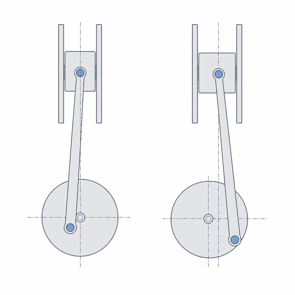
There are two positions in the turn where the crank and the rod become aligned, one at each end of the piston's stroke. These are the dead centers, and understanding them explains why this mechanism, depending on how you drive it, can fail to start.
The torque between crank and piston depends on the angle between the rod and the crank. When the two are aligned, the rod's force passes exactly through the crank's axis of rotation: its lever arm is zero, and so the torque is zero. At that same instant, because the rod lies aligned with the axis of the guide, its side thrust on the piston is also zero — the dead centers are the points of minimum lateral load, not maximum. But the useful torque vanishes: however hard the piston pushes, it produces no rotation.
This has a practical consequence that depends on where the motion enters. If the input is the crank — continuous rotation, the usual case — there's no starting problem: the shaft sails straight through the dead centers. The problem appears when the input is the piston: a crank-slider driven from the piston and stopped at a dead center won't start on its own, because in that position the linear push produces no torque. In a real engine this is solved in one of two ways. One is inertia: a flywheel stores kinetic energy in the rotation and the part coasts straight through the dead center without needing torque at that instant. The other is phasing: two or more cylinders, with the cranks set at an angle to one another, so that when one is at its dead center the other delivers torque. If your design has a single cylinder and you drive it from the piston, keep this in mind. Don't expect useful torque at the ends of the stroke, and give the system a flywheel with some mass if you want the rotation to sustain itself.
Offset: silencing the clatter at reversal
There's a geometric trick that almost always pays off: shift the axis of the piston guide sideways relative to the crank's center of rotation. This is the offset (the crankshaft offset), and it means the piston's line of motion no longer passes through the crank center, but sits a little to one side.
Here's why: the side thrust we saw earlier isn't constant — it reverses direction over the course of the turn, because the rod tilts one way on the out-stroke and the other way on the return. At the instant that lateral component crosses zero and changes sign, the piston lifts off one face of the guide and seats against the opposite face. If there's play between the piston and the guide — and in FDM there always is — that jump from one wall to the other is a hard knock: the characteristic clatter at reversal. The offset doesn't eliminate that zero crossing; the rod still switches sides. What it does is shift the instant of the bearing-face change relative to the dead center, so that the piston changes face when the axial force is lower and the knock is softer. The motion gains smoothness right where the noise was most noticeable.
In exchange, the offset introduces something the symmetric mechanism didn't have: the out-stroke and the return stop following the same law. Together with the rod length, the offset is the other fine dimension for tuning the mechanism's behavior: a longer rod and a well-chosen offset reduce the side thrust and clean up the clatter, at the cost of a bit more space and a stroke that is no longer perfectly symmetric between out-stroke and return. Decide what matters more to you — symmetry of the motion law, or quiet at reversal — and size accordingly.
Printing the joints: the pins make or break it
This is where the mechanism is won or lost in FDM, because the two joints — crank to rod, and rod to piston — are pins, and a printed pin has two enemies: badly chosen clearance and the wrong layer orientation.
Each joint is a shaft turning inside a hole, so it's sized as a pin-socket with a running clearance: the hole opened up just enough for the pin to turn free but without play. If it's too tight, the joint seizes or the rotation is jerky; if it's too loose, you get play that translates directly into clatter every time the push reverses direction. As a starting point before calibrating, a diametral clearance of 0.2 to 0.4 mm is usually a reasonable opening, but that figure isn't copied from a machining table: it depends on how your printer shrinks holes and fattens shafts, and the exact number comes from calibrating your machine, as detailed in Tolerances for moving parts.
You can print the pins separately and insert them, or solve the joint print-in-place, modeling the clearance gap between shaft and hole so they come off the bed already assembled. But the print-in-place of a horizontal shaft isn't free: the top face of the shaft comes out as an overhang — rougher and tighter — and the bottom tends to fuse with what's beneath it, so the effective clearance isn't symmetric and usually needs more margin than an inserted pin. If you can, orient that shaft vertically, or plan on extra cleanup and clearance.
The other half of the job is orientation, and here there's a genuine trade-off. A pin transmits its load perpendicular to its own axis, and if you print the bar so that this load pulls between layers, the pin or its housing delaminates: the crack follows the weak plane between beads, not the solid plastic. Laying each bar down with its load plane in the XY plane makes the forces travel along the beads rather than peeling one layer off the next. But that same orientation puts the hole's axis horizontal, and a hole printed horizontally comes out less round — it goes oval where the roof bridges — than one with its axis in Z. You have to choose: a strong bar with the load plane in XY, or a more cylindrical hole with its axis vertical. When the load rules, prioritize the XY plane and compensate the hole with clearance or a bushing; the reason for the anisotropy and how to orient is covered in Layer orientation for motion.
When to choose it and how it fails
The crank-slider is your mechanism when you need continuous rotation converted into reciprocating linear push — a pump, a saw, a compressor — or the inverse conversion, a piston driving a shaft. But it isn't the only way to turn rotation into reciprocation, and it's worth knowing when it isn't the best. If all you need is pure translation and a perfectly sinusoidal motion, without the deviation the finite rod introduces, the Scotch yoke offers exactly that. Its price in FDM is a different one: the slider runs continuously inside a printed slot, which ovals with use, so it delivers the clean sine in exchange for worse slot durability. The choice is dictated by the motion law you're after: the crank-slider when you want the robust pin-based transmission and can tolerate the deviation from the sine; the yoke when you want the pure sine and can keep the slot alive. There's no absolute winner — only the motion you want.
Learn the failure modes before you meet them with the mechanism already built. The first is play in the pins: any excess slack in the joints concentrates at the stroke reversal, when the push inverts direction and all the play is taken up at once; it's the audible clatter that gives away a loose fit. The second is rod buckling: the rod works in compression for half a turn, and if you've made it long and slender to reduce side thrust, that same slenderness makes it prone to buckling under the axial load instead of transmitting it straight. At the scale of an FDM part, elastic buckling rarely dominates over delamination or crushing of the joint, but keep an eye on it if the rod ends up very slender: give it enough section that the slenderness ratio doesn't run away. The third is wear of the piston guide from the side thrust you already know: the transverse component of the rod's force rubs the piston against its guide every cycle, and in plastic against plastic that's material disappearing and play growing. Raising L/r, adding offset, and — if needed — adding a hard sliding surface are the three levers to tame it.
Each of those three levers comes back to the same place: the tenths of a millimeter of clearance you choose at each pin and the orientation in which you pull each bar off the bed. If the assembly clatters or seizes, start there. Tolerances for moving parts is the article that turns the function of each joint into the exact gap you should model.