Escapement and cam indexer: clockwork and precision
There's a class of mechanism whose job isn't to move something from A to B but to release it in exact doses—one tooth, one step, one position—and then brake again. This is precision intermittent motion, and two parts push it to opposite ends of the spectrum. The escapement measures time by letting one tooth slip free for every swing of a pendulum. The cam indexer advances a table by one exact step per turn of the drive shaft and holds it form-locked for the rest of the rotation. One keeps time, the other indexes, but at heart they do the same thing: they turn a continuous torque into discrete, synchronized advances. And both will teach you, without mercy, where your printer's precision ceiling really is.
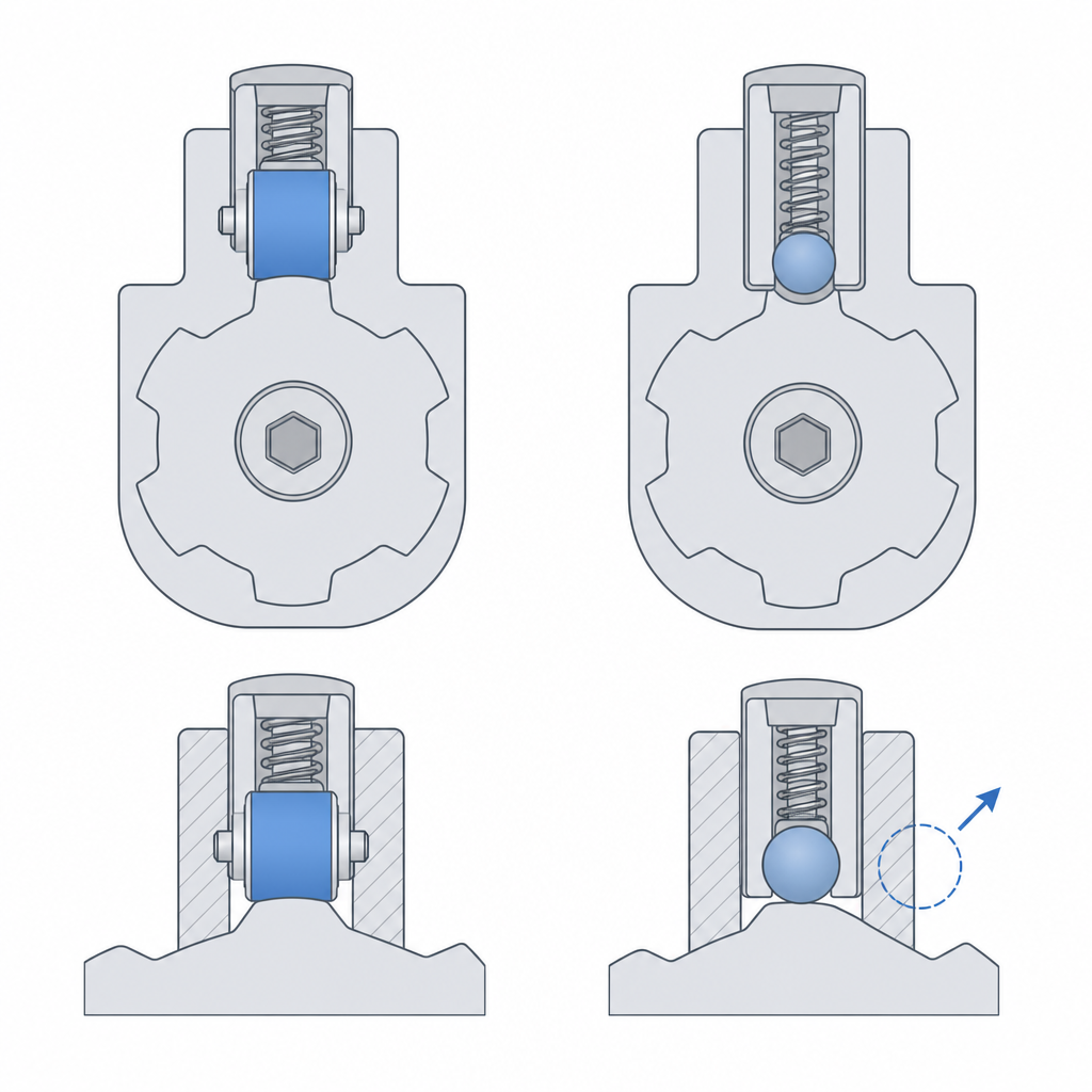
The escapement: releasing one tooth per swing and returning the impulse
The escapement does two jobs at once with the same part, and that's where all its elegance lives. The escape wheel receives a continuous torque from the gear train—ultimately from a weight or a spring—and pushes constantly. The anchor, a lever with two pallets at its ends, rocks on its pivot at the rhythm of the oscillator (pendulum or balance wheel). On each half-swing, one pallet withdraws and lets a tooth of the wheel escape; the wheel turns by that step and, before it can overrun, the other pallet has already dropped to intercept the next tooth. One advances, one brakes. That cadence is what keeps time.
It pays to pull the phases apart, because the behavior is settled in the details. When one pallet releases its tooth, the wheel turns until the next tooth lands on the other pallet: this is the drop, the only span where the wheel runs free. That tooth lands on the locking face of the pallet and stays there, sliding without delivering any energy, while the oscillator completes its travel and returns. And only at the very end, when the pallet begins to withdraw, does the tooth move onto the impulse face—the inclined plane—and give the anchor a measured push. Drop, lock, impulse: three distinct phases on each half-swing, and the escapement depends on keeping them distinct.
If the anchor only braked, the pendulum would lose amplitude to air resistance and pivot friction until it stopped. Hence the impulse: that push against the inclined face, small and precisely measured, replaces exactly the energy the oscillator dissipates each cycle. The continuous torque source doesn't dictate the rhythm; the oscillator does, at its own natural frequency. The torque only keeps the motion alive. The escapement translates the pendulum's free oscillation into counted steps and, in exchange, returns the energy that keeps it running.
The kinematics come down to angles measured in tenths of a degree: the angle of the impulse face, which sets how much energy enters per cycle; the angle of the locking face; and the draw, a slight incline that pulls the anchor against its tooth during locking and keeps it seated rather than letting it bounce loose. Don't confuse draw with recoil, the backward rebound of the escape wheel—characteristic of the recoil escapement and absent in a deadbeat escapement. Draw is what keeps the mechanism secure, and it's the first thing you lose when you print one.
The cam indexer: one exact step and form lock
The cam indexer solves a different problem with the opposite philosophy. There's no oscillator in charge here: the drive shaft turns continuously and at constant speed, and what you want is for a table or turret to advance one exact step per turn and then hold absolutely still for the rest of the rotation. A drum cam—a cylinder with a curved groove cut into its surface—or a globoidal cam achieves this, acting against a turret with rollers spaced around its periphery.
The key lies in how the input rotation is split. During one portion of the drum's turn, the active section of the groove pushes the rollers sideways and turns the turret by its exact step: that's the indexing phase. For the rest of the turn, the groove runs parallel, with no component that moves the turret: that's the dwell. And here's the trick that sets it apart from a Geneva (Maltese cross) mechanism: the groove doesn't just stop pushing, it captures the roller on both sides. During the dwell the roller is trapped between the two walls of the groove, so the turret is locked by the cam's own shape (form lock), with no external brake, no detent, no spring. The part holds itself in place. In its simplest form—a single-start drum—one step drops per turn of the shaft; with multiple starts or more stations, the ratio changes, but the principle is the same.
That gives you two things a Geneva mechanism won't hand you. One is that you draw the motion law—the acceleration and deceleration of the step—into the groove profile yourself, and you can make it smooth so it doesn't jolt a heavy load. The other is backlash control: because the roller always rides seated between the walls of the groove, there's no dead gap through which an indexed table rattles or drifts. That said, a single groove needs some clearance for the roller to roll, so absolute zero doesn't come from here: true zero backlash is achieved with a conjugate cam and a preloaded double roller, where two opposing flanks press against each other and leave no play at all. All of this comes at the cost of geometric complexity. The groove is a three-dimensional curve on a cylindrical surface, not a flat profile you define in one stroke, and that changes everything when it comes time to print.
Printing each one in FDM: where precision breaks down
Here both mechanisms collide head-on with the process, and it's worth being honest about how far you get. The escapement lives on tiny, very precise flanks: the impulse and locking faces of the pallets, the flanks of the wheel's teeth. The staircase effect of layer deposition discretizes those surfaces into steps. A face that on the drawing is a clean ramp emerges, in the part, as a staircase of steps one layer height tall; and over those steps the tooth doesn't slide, it jumps and scrapes. Print the escapement flat in XY—the plane of the wheel and the plane of the anchor parallel to the bed—at the finest resolution your machine can manage. Printed that way, each tooth's outline is traced by the bead in-plane and comes out far truer than a flank built up by stacking layers in Z.
The trade-off is that this same plane leaves the pivots vertical, in Z, which is where a printed hole comes out worst: oval, stepped, and with more friction in exactly the spot the oscillator is least forgiving. Plan for this and handle the pivots separately: they're the first candidate for embedded hardware—a small bearing, a ground pin—rather than trusting it all to a printed hole (developed in Embedded hardware: magnets, bearings, and inserts).
Even so, be realistic about the timekeeping. Plastic-on-plastic friction at the pallets is high and variable, the staircasing introduces friction that changes from one tooth to the next, and all of that alters the impulse reaching the oscillator. But the failure you'll see first isn't rate drift: it's the loss of draw. With loose pivots and imprecise faces, the anchor stops sitting firmly against its tooth during locking, bounces, and the wheel lets one extra tooth escape—the mechanism races ahead and skips. A printed escapement works—it oscillates, escapes, counts—but its clock precision is demonstrative, not metrological: good for showing the physics, not for telling the time.
The indexer poses a different and, in some ways, more serious modeling problem. You don't lay out that three-dimensional groove on the drum by hand: you need a cam generator that computes the curve from the motion law you want, the number of steps, and the roller diameter. And once it's modeled, the print orientation determines whether the part is usable. A groove that wraps a cylinder generates, depending on how you orient it, overhanging walls and zones the slicer will want to prop up with supports; and a support inside the groove the roller has to run through is exactly what you don't want, because it leaves the contact surface rough where it most needs to be smooth. Orient the drum so the active flanks of the groove are as self-supporting as possible, and expect it to be one of the parts that needs the most orientation attempts before it prints cleanly.
The groove-to-roller clearance: neither binding nor rattling
In the indexer, all the tuning concentrates on one dimension: the clearance between the groove and the roller. And it's a clearance with a contradictory demand, because the same groove has to let the roller run during indexing and trap it firmly during the dwell. Too tight, and the roller binds in the active phase: the mechanism jams or demands an input torque that deforms the cam. Too loose, and the form lock stops being firm—play appears between the groove walls and the roller that is, precisely, the backlash you wanted to avoid. The indexed table settles at each stop with a small wobble, and you've built an expensive Geneva.
You get your starting number the way you would for any other sliding fit on your printer—on the order of 0.15 to 0.25 mm per side so it rolls without jamming—but keeping in mind that a printed cylindrical hole comes out narrower than its nominal dimension, so the clearance you draw isn't the one you'll have. An open groove doesn't close up the same way every time—it depends on the direction of the beads and the extrusion width—so here, more than anywhere, you have to measure: work from the groove as measured on your part, not the nominal one. The method for pinning down your real clearance is in Tolerances for moving parts. And if you can, put a real metal roller—a ground pin or a small bearing—in place of a printed one: by rolling instead of dragging, it sharply reduces sliding wear and keeps its own diameter constant, so it lets you tune the clearance against a surface that doesn't change with every turn. That said, a metal roller against a plastic wall concentrates the wear on the soft wall; it doesn't magically protect the wall, it only eliminates the drag friction.
Wear is the failure mode that catches up with both mechanisms in the long run. In the escapement, the pallets wear where the tooth rubs them, and as they do they change their impulse angle: the rate drifts and, in the worst case, the oscillation stops because there's no longer enough energy reaching it to replace what it dissipates. In the indexer, the groove wears where the roller bears, and that rubbing opens up the clearance: the backlash the form lock kept in check returns, and the step starts landing imprecisely. In plastic against plastic, both effects set in sooner than you'd like. That's why, the moment the mechanism has to last rather than just demonstrate, the rolling contact points and the pivots are the first candidates for embedded hardware.
If what you want is to index but without fighting a three-dimensional groove, the simplest variant is the Geneva (Maltese cross), which achieves the step-by-step with flat profiles at the cost of the smoothness of the motion law. Either way, it's worth being clear on Layer orientation for motion: in these parts the direction in which you stack the layers determines whether the contact flanks come out smooth or stepped—and that, in the end, is the difference between a mechanism that measures and one that merely moves.