Layer orientation for motion
A printed part looks solid, but it isn't: it's a stack of beads welded one on top of another, and that weld is never as strong as the plastic it joins. Within a layer the material is continuous; between two layers there is only the seam where one bead fused to the one below while it was still hot. On a phone stand that difference goes unnoticed. In a mechanism it decides everything: a hinge meant to survive a thousand openings delaminates on the third — always for the same reason. The part was loaded across the layers instead of along them.
FDM is anisotropic, and not by accident
Anisotropic means the part isn't equally strong in every direction. In FDM the asymmetry is large and predictable. Along the XY plane the material is essentially continuous: the bead is a thread of hot-extruded plastic, with no interruptions. In the Z direction, by contrast, each layer rests on one that has already cooled, and the bond depends on how much heat softened the surface below when the new bead arrived. That interlayer weld typically lands somewhere in a wide range — on the order of 50 to 90 percent of the in-plane strength, depending on material and parameters — and extrusion temperature and cooling are what move it most within that band.
The material matters, but not the way people usually assume. PLA is stiff and its Z adhesion isn't bad, but it fails in a brittle way. PETG, which cools more slowly, tends to weld better between layers. The ones that truly delaminate are ABS and ASA without an enclosure, or poorly dried nylon: they cool too fast or bubble moisture into the seam. Before you trust any orientation, dry hygroscopic material; a wet spool delaminates even when the part is perfectly oriented.
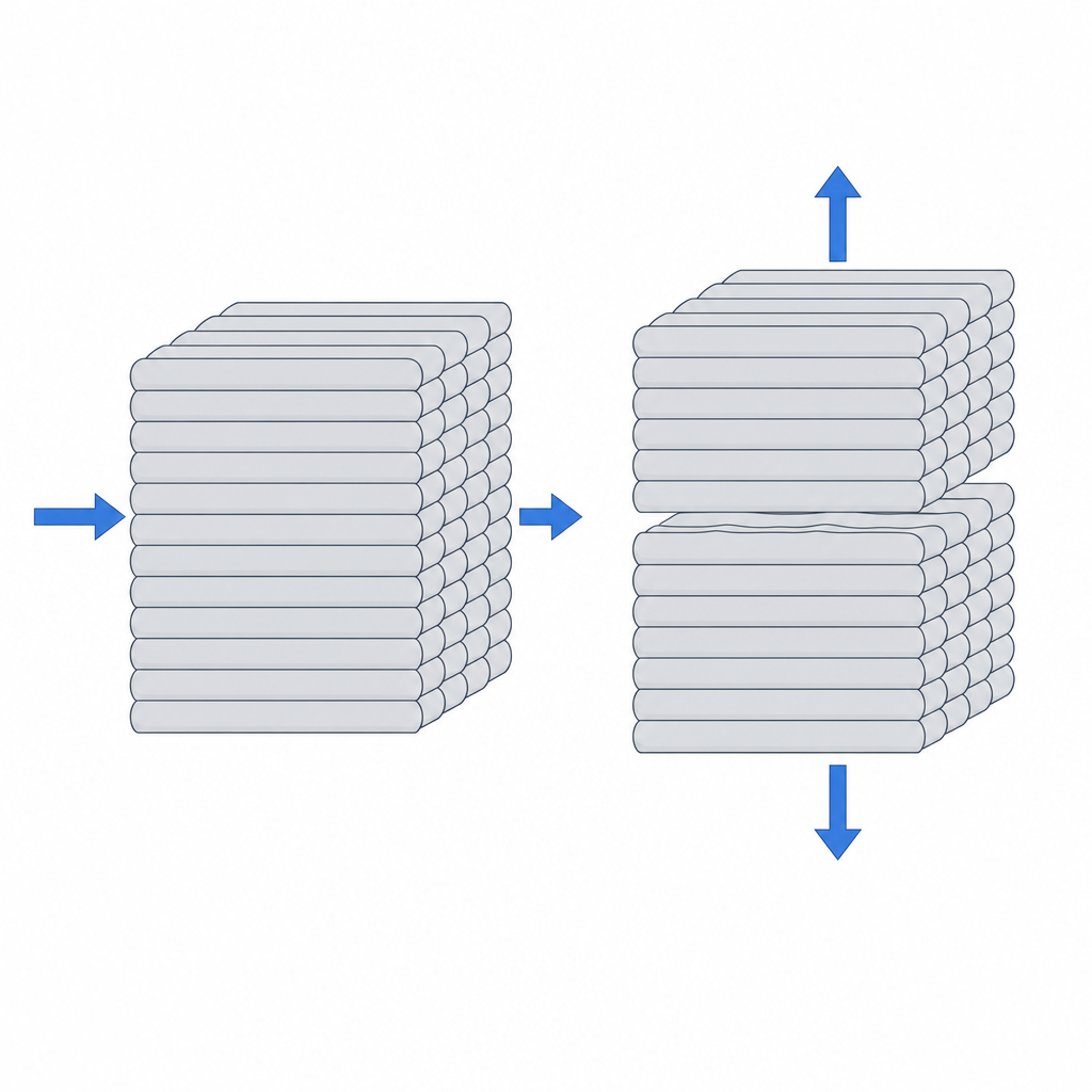
The weak plane is always the same: the interface between two layers. Picture it as a stack of glued sheets of paper. Tearing one sheet across costs effort; peeling apart two sheets that share only a thin film of glue does not. An FDM part behaves the same way. The whole discipline of orienting mechanisms comes down to one question: which way does that bond plane face, and is the working load trying to open it?
The rule: keep the load in the plane of the layer
Before you model any part that moves, ask the physical question, not the geometric one: which direction does the force pull, and does it land on a joint between layers? If the service bending or tension runs in the plane of the layers, the material works at its full strength. If it runs across them, you're working against the weld, and the weld is what gives first.
There are two typical ways to get this wrong, and it helps to recognize them by their failure mode:
- Anything that flexes by bending along a layer line delaminates. An element that bends repeatedly — the arm of a snap, the leaf of a living hinge — opens the seam between beads just like peeling those two sheets of paper apart. It doesn't wear out — it peels, and it usually warns you first: visible whitening or cracking at the seam before the final break.
- Anything that takes tension normal to the layer plane peels the layers apart. A pin or a tooth printed "standing up" works in bending: the tension side of the bending moment lands right on the interface between layers. The crack runs along the seam and the part snaps cleanly, with no prior deformation.
The living hinge: no margin for error
A living hinge is a thin section of plastic meant to bend thousands of times in the same spot. It's the example where orientation is not a nuance but the line between working and not working.
Start with the material, because here it matters more than orientation. PLA is a poor candidate: it's stiff and brittle, and under repeated bending it cracks within a few dozen cycles no matter how well it's oriented. Real living hinges are made in polypropylene (PP) or polyethylene, and secondarily in TPU, PETG, or nylon — materials that tolerate repeated plastic deformation without cracking.
Folding stretches and compresses the material along the bend. For that stretch to happen within the strong plane, the hinge axis must lie along a layer, and the leaf must be printed flat on the bed. The key detail is the direction of the beads in the bending zone: they should run parallel to the bend axis, crossing it continuously, with no transverse seams cutting across the flex line. The slicer won't guarantee that on its own; in a narrow web, force the perimeters so the contour follows the flex instead of filling it with beads that cross at 45 degrees.
Thickness matters as much as orientation. A web of 0.3 to 0.8 mm, printed with 1 or 2 continuous perimeters — not infill — bends well and prints with a full bead. Going thinner leaves it too fine to hold a continuous bead, and prone to snapping.
Print it on edge — with the bend stacked between layers — and the hinge delaminates on the first or second cycle: the fold opens the weld between beads directly, and that weld isn't built to work in repeated bending. No material or layer height fixes it: the failure is in the seam geometry. That's why the editor warns you about orientation on parts like this.
Snaps and cantilevers: the arm bends in the plane
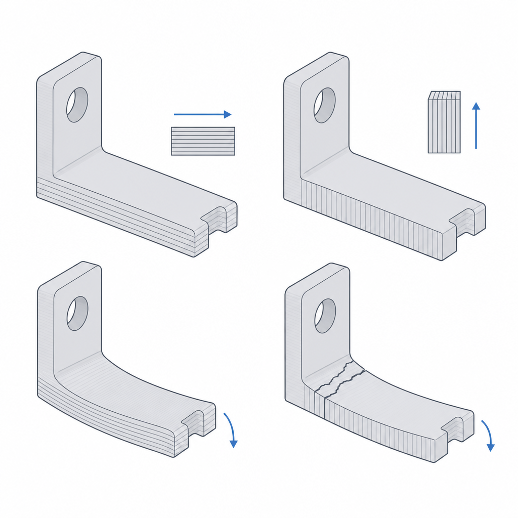
A cantilever snap (an arm that flexes to catch and springs back into place) is physically a beam that bends every time you assemble or disassemble the part. The outer fiber of the arm stretches; the inner one compresses. If that bending coincides with the plane between two layers, each cycle opens the seam a little more, and the arm breaks after a few cycles.
The correct orientation follows the same idea as before: let the arm bend in the plane of the layers, so that the stretch of the outer fiber runs along continuous beads instead of trying to peel them. And as with the hinge, force the perimeters to follow the arm: a thin arm filled with crossed beads flexes far worse than one made of continuous contours.
Watch the material too. In PLA, a well-oriented snap survives dozens or hundreds of cycles of occasional use, but PLA cold-flows (creep): if the catch is left permanently flexed, it loses retention force over time. For many cycles, or for a catch that stays under load, move to PETG, PP, nylon, or polycarbonate. When you size the catch clearance, remember it also depends on the real FDM tolerance; that's covered in Tolerances for moving parts.
Pivots and pins: it's bending, not shear
A printed pivot resists differently depending on where the load comes in. A pin lying down, with its axis parallel to the bed, has continuous fibers along the bead opposing the force, and resists well. The same pin printed standing up, with the axis vertical, fails by the bending moment at its base: the tension from that moment lands normal to the layer plane and opens the seam far sooner. It isn't pure shear — FDM isn't especially weak in shear across layers — it's the bending tension that peels the interface.
Here it's worth qualifying a common belief about layer height. Lowering it — from 0.2 to 0.1 mm — improves the quality of the hole wall: the cylinder comes out rounder, with finer steps, and the shaft fit is more predictable. It does affect the Z bond somewhat: thinner layers reflow heat onto the one below better, though in exchange they add more interfaces, and the net effect depends on the part. What layer height does not do is eliminate the anisotropy: the bond plane is still the weak one. To govern directional strength, the two big levers are orientation and temperature — not layer height — since a hotter hotend and less fan weld better between layers.
| Element | Robust orientation | Why |
|---|---|---|
| Living hinge | Flat; bend axis along a layer, beads parallel to the bend | Folding stretches the strong plane, not the seam |
| Cantilever snap | Arm bending in the plane of the layers | Bending doesn't peel the bond between beads |
| Pin / pivot | Axis parallel to the bed (lying down) | The bending moment doesn't land normal to the interlayer interface |
| Axially loaded shaft | Avoid pure Z tension | Tension separates layers directly |
When you have to print standing up: an explicit trade-off
The most convenient orientation doesn't always win. Sometimes the functional face — the track something slides on, the wall of a hole that must finish round and strong — only prints well if you stand the part up, even if that forces supports and worsens other surfaces. It's a legitimate trade-off, as long as it's deliberate: you accept supports and a poorer finish on the secondary faces in exchange for the face that matters landing in the strong plane, with the load traveling within the layers.
The strongest orientation rarely coincides with the one that prints support-free or with the best surface. In a mechanism, strength wins. Decide the print posture first from how the load travels, and sort out the finish afterward: chamfers, the best face down, supports where needed. Reorienting an already-modeled part almost always forces a redesign.
The physics behind that weld between beads, and why force direction decides the failure mode, is in Layer adhesion and anisotropy. You'll see how orientation combines with overhangs and supports in Orientation and overhangs. And when you move from orienting to sizing the clearances that let parts move, continue with Tolerances for moving parts.