Friction drive, Bowden, and block and tackle: three lesser-known flexible drives
When you think about transmitting motion without a gear train, the first thing that comes to mind is the timing belt. But there are three more modest mechanisms that solve problems the belt doesn't, and all three fit comfortably inside an FDM printer: a wheel that drives another purely by contact, a cable that runs inside a sheath and turns corners, and a set of pulleys that turns a small motor into a lot of force. None of them needs teeth or precise timing. What they need is for you to understand the physics that makes them work and the point at which they fail, because each fails in a distinct and very recognizable way.
The friction wheel drives by grip, not by teeth
Set two wheels spinning with their rims touching, and the first drives the second. There is no meshing: the only thing moving the driven wheel is friction at the line of contact — the grip between the two surfaces. The transmission ratio comes from the ratio of diameters, because the tangential speed at the contact point is shared by both wheels. But unlike a gear tooth seating into its mating space, that ratio is never exact. Even well below the slip threshold there is elastic microslip in the contact zone—the material deforms and recovers as it rolls—so the driven wheel always turns slightly less than pure geometry would dictate, and how much less depends on the load. The friction wheel does not guarantee a turn count; it guarantees motion as long as the required torque does not exceed what friction can transmit.
That "weakness" is also its greatest strength. Because the contact slips under an overload, the friction wheel is a natural torque limiter: if something jams on the output side, the wheels slip instead of breaking a tooth or burning out the motor. And because there are no teeth to mesh and clatter, it runs quietly and is cheap to print: two cylinders and two shafts, nothing more. The catch is that the torque it transmits is bounded by the friction coefficient times the force with which you press one wheel against the other. If you need only modest torque and want it quiet, you have margin to spare; if you demand real torque, it slips and can't deliver.
The lever for raising that ceiling is μ, the friction coefficient. PLA against PLA is not especially slippery — its μ runs around 0.3–0.4, nowhere near PTFE. But the friction you can actually put to work is low, because the normal load printed shafts can take is modest and because the track polishes itself with use. Here FDM gives you a clean fix: a band of TPU or an O-ring seated in the track of one of the wheels. The elastomer bites the other track and multiplies the grip without having to squeeze the shafts any harder. Model a groove in the rim of the wheel and seat the O-ring there, or print the rim directly in TPU over a rigid core.
The elastomer isn't free, though. It deforms under the normal load, which widens the contact patch and shifts the effective rolling radius a little—that is, it further erodes the turn accuracy you never really had to begin with. And TPU under sustained compression slowly flows (creep) and gradually loses the preload you mounted it with. You accept this because in return it gives you the torque; but if what you were after was rotational precision, the friction wheel was the wrong choice, band or no band.
That preload, moreover, isn't free structurally, either. The force with which you press one wheel against the other loads the shafts sideways all the time, not now and then. In FDM that flexes thin shafts and wears the housing, and as it softens, the contact force drops and the torque with it. A friction wheel asks for rigid shafts and bearings able to take a constant radial load; size them for that permanent preload, not for the weight of the wheel.
The Bowden carries motion along curved paths
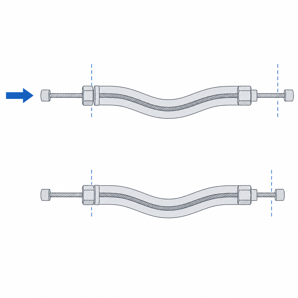
A Bowden cable is an inner core—usually steel—that slides inside a sheath. The idea seems trivial until you see what it enables: transmitting motion from one point to another along a curved path, with no shafts, no idler pulleys, and no need for the run to be straight. It's what bicycle brakes use to carry the pull of the lever to the caliper while clearing the handlebar and frame, and what a Bowden-head printer uses to push filament from a fixed extruder to a moving hotend.
The physics that makes it work is the conservation of sheath length. With the sheath firmly anchored at both ends, its length between anchors does not change even if the routing curves. If you push a millimeter of core in at one end, that millimeter has to come out the other, because no more core can fit inside the sheath than is already there. The displacement is transmitted from one tip to the other regardless of the routing, straight or full of curves. That is what no rigid shaft gives you: motion that turns corners. And it's worth underlining the condition, because it's where half of printed Bowden setups fail: if the sheath is not held axially at both ends and can run inside its anchor, the core stops being transmitted whole and the system goes spongy. Anchor the sheath, not just the core.
You pay for it in two ways, and they're worth naming, because the entire limitation of the system lives in them. The first is internal friction: the core rubs against the sheath wall at every curve, and the tighter the radius, the harder it presses and the more friction it adds. That friction eats part of the displacement and forces you to pull harder than you should. The second is the combination of the radial play between core and sheath with the axial compression of the sheath itself under load: a smooth PTFE sheath — the most common, thanks to the very low μ of its inner wall — is relatively soft, and under the pushing force it bows and shortens before it moves the other end. Those two things create a dead zone: you begin to actuate and, for an initial portion of the input, the output doesn't move, because first the core has to be tensioned, the sheath has to seat and compress, and the static friction has to be overcome. In a Bowden printer that dead zone is exactly what produces the backlash in the filament — the extruder drags and releases too much of it on retractions.
There's a nuance that changes the design depending on the direction of the load. A bike brake works the core in tension: you pull on it and it stays straight and taut inside the sheath. A Bowden extruder does the opposite, it pushes the filament in compression, and a slender element in compression inside a radial gap buckles: the filament bows and presses against the wall instead of advancing, which adds dead zone and, in the worst case, it coils up or jams. That's why a Bowden in push is always more demanding about radial play than one in tension: there the gap isn't just slack, it's room to buckle. Fit the inside of the sheath to the core as tightly as sliding allows when you work in compression.
To anchor the ends with precision—and to seat the tube so it neither moves nor runs—you lean on the same tolerances as any sliding or press fit, which you'll find in Tolerances for moving parts.
The block and tackle trades travel for force
A block and tackle is a set of pulleys through which a single cable passes several times between a fixed block and a moving one. If the cable makes n passes supporting the load, the load's weight is shared among those n strands, and each strand carries only the nth part. In the ideal case, pulling on the free end with a small force lifts a weight n times greater. It's the oldest way to gain force without a reduction gearbox.
What keeps the trade honest is the conservation of work. You get nothing for free: what you gain in force you pay, exactly, in travel. If you multiply the force by n, you have to pull n meters of cable for every meter the load rises, because the n strands that shorten are all fed by the cable you reel in. The input work equals the output plus the losses: in the ideal limit, the product of force and distance stays constant, and in reality friction takes a share. That's why a block and tackle is ideal when you have a small actuator and plenty of travel available but little force: a printed lift, a tensioner, a gate that rises slowly but without jamming. You trade speed and stroke for force.
And here's the nuance that decides whether your printed block and tackle works or not: the real mechanical advantage is never n. Every pulley that rubs on its axle takes a percentage of the force, and that deduction accumulates pass by pass. With a plain sliding plastic bushing on a plastic axle—high μ—the loss per pulley is considerable, and multiplied across several strands the effective advantage can fall well below n. This is no minor point: for large n, a plain plastic bushing is nearly unworkable. The embedded bearing is the default option in a block and tackle that actually multiplies, not the fallback for when the load gets heavy. You size the housing for that bearing or bushing like any other fit, and you'll find it in Embedded hardware: magnets, bearings, and inserts.
The other piece that decides the outcome is the cable itself and where it runs. The pulley groove has to retain the cable: deep enough and at the right angle for the cable to settle into the bottom and not climb the flank. But there are two spots people forget, and they're exactly where these setups blow out. One is the pulley radius: if it's small relative to the cable diameter, you force the cable to bend tight on every pass and fatigue it until it breaks; give the pulley plenty of radius for the cable you use. The other is the anchor for the dead strand, the fixed end of the cable: there the tension of the whole load concentrates, and it's where the plastic tears if you anchor it with nothing more than a plain hole. Anchor it with plenty of material around it and, better still, with the cable taking a wrap or a knot that spreads the load — not in shear against a thin wall.
Which one to reach for
All three are lesser-known flexible drives because none of them gives you the exact ratio and clean torque of a gear or a timing belt. But each solves something the big ones don't, and the choice is straightforward once you know what matters most for your mechanism.
Choose a friction wheel when you want the simplest thing possible and turn accuracy doesn't matter: quiet, two cylinders, a torque limiter thrown in. You know it will slip under overload, and often that's exactly what you want. Choose a Bowden when you need to carry motion from one place to another along a path that isn't straight: at a distance, turning corners, with no intermediate shafts. In return you accept the dead zone and the backlash, which is the toll for transmitting inside a sheath. And choose a block and tackle when what you lack is force and you have travel to spare: you multiply the push of a small actuator by the number of strands, paying for it in cable pulled and in the friction of the pulleys.
None of them replaces a gear when you need exact position and guaranteed torque. But when you don't need those, building a gear train is over-engineering the problem. The wheel that rubs, the cable that turns corners, and the pulleys that share the load do their job with a fraction of the parts, and they fail in ways you already know how to recognize and prevent.