Printed joinery: dovetails and joints
Your bed is 256 mm on a side and the part you need measures 400. Or it does fit, but the only sensible orientation leaves an impossible overhang — or points the layers straight at the load. Woodworking solved this problem for solid timber centuries ago: instead of a fastener, a shape that aligns two parts and carries the load between them. Those same profiles — dovetail, finger joint, half-lap — work just as well in plastic, and they are the clean way to split a large object into printable pieces that become one again, without a single screw.
Splitting a part is design, not damage control
When an object won't fit on the bed, the first instinct is to slice it in half with a flat cut and glue it blindly. That throws away the best of FDM. If you're going to split the part anyway, the cut is an opportunity: you get to choose where the joint falls and what shape it takes, and with that you control three things at once. First, each half rests on the bed in the orientation that leaves the layers strong where the forces go (see Layer orientation for motion). Second, the two halves self-align on assembly, without having to hold them by hand while the glue sets. And third, the joint carries load from one part to the other instead of trusting everything to a thin film of adhesive.
A good woodworking joint does all three. So the question isn't "how do I glue this?" but "what profile goes in the cut so it positions itself and carries load?"
Dovetail: lock by sliding, not by pulling
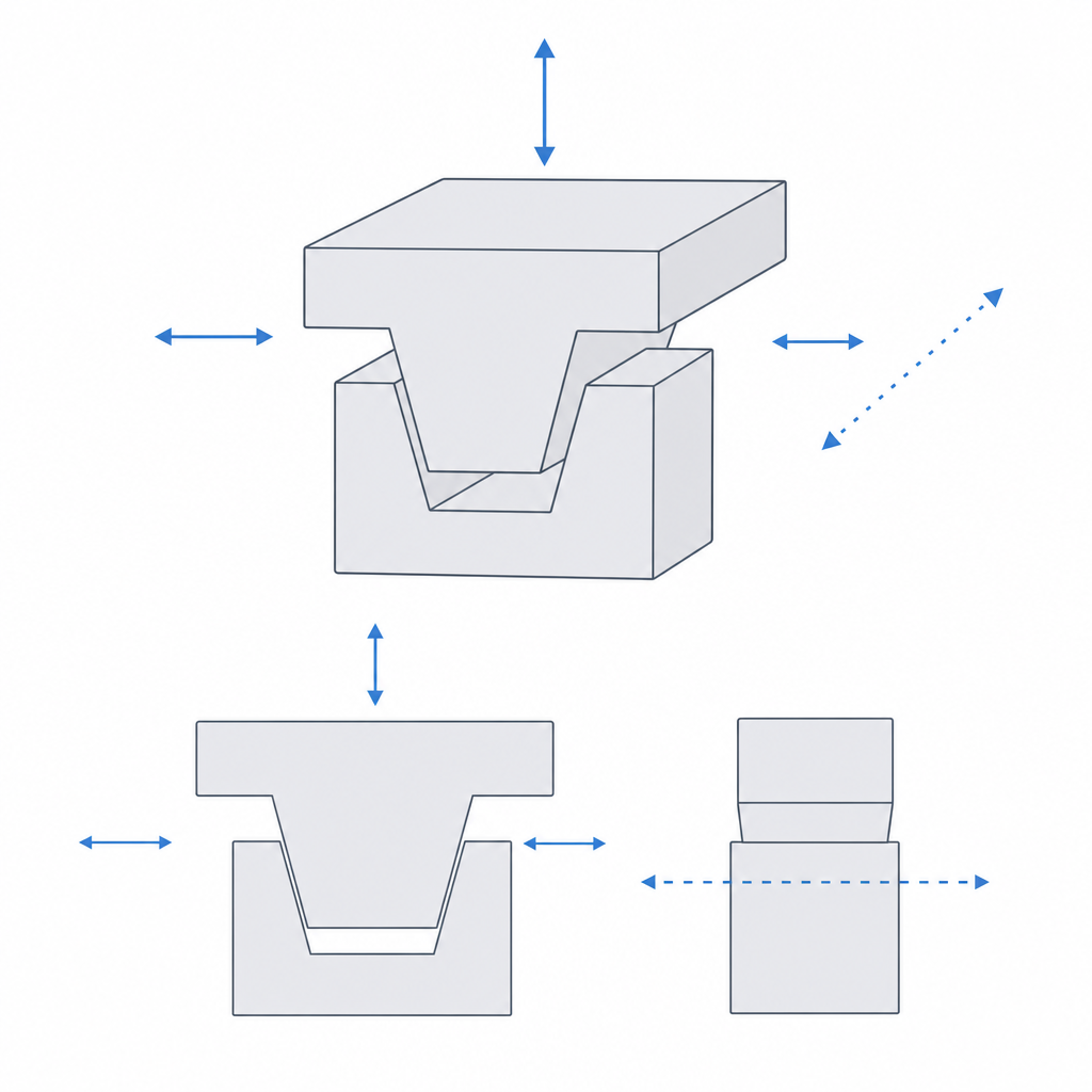
The trapezoidal profile is the standout of the family. Once seated, the dovetail locks against separation on one axis: however hard you pull perpendicular to the joint, the angled faces of the trapezoid resist and it can't come out. It only escapes the way it went in — sliding along the rail. That is exactly its strength, and at the same time the rule that governs it: because it assembles by sliding, a dovetail is a sliding fit, not a press fit.
Making it a sliding fit doesn't mean changing the shape of the trapezoid between rail and groove: the profile is the same, with the same angle, and what you do is shrink the male side by a clearance per side — on the order of 0.10 to 0.20 mm in PLA with a 0.4 mm nozzle — only on the sliding faces, so it goes in without binding but without play. If you changed the angle instead of offsetting the profile, the angled faces would stop matching and you'd lose precisely the lock that is the joint's whole reason to exist. It's exactly the clearance of any mechanism that moves: work out the figure with Tolerances for moving parts and pick the fit family with Choosing the fit: clearance, transition, interference.
The layer trap: orient the wedge so it doesn't open
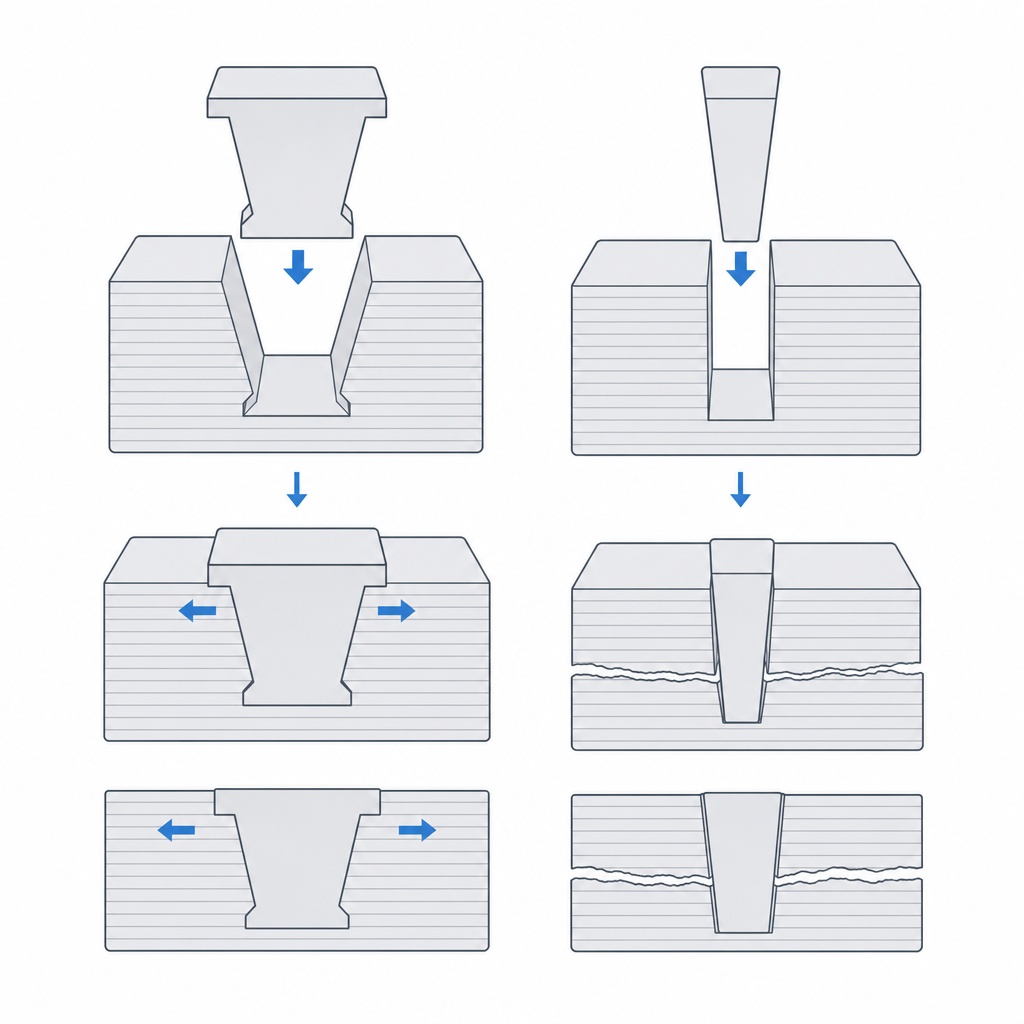
This is where printed joinery diverges from wood. Wood is strong in every direction; an FDM part isn't. It's strong along its layers and weak between them: it delaminates before it breaks across (the physics is in Layer adhesion and anisotropy). The dovetail's wedge is what takes the separation load, so the critical question is: which way do the layers point in that wedge?
The good rule isn't "lay the rail down" and nothing more, but this: the separation force must lie in the plane of the layers, never perpendicular to it. If you print the rail standing up, with the sliding direction vertical, the angled faces of the trapezoid are formed by stacked layer edges, and the force trying to open the joint pulls between layers. That's the weak direction: the dovetail delaminates and opens at a fraction of the load it should hold. Orient the part so the separation runs through the layers in their plane, not prying one layer from the next. The wedge face will still have some stepping for being angled — that's unavoidable unless you stand it vertical — but those steps are cosmetic; what decides whether the joint holds or fails is the direction of the load relative to the layer plane.
Finger joint and half-lap: gluing surface and alignment
Not every joint assembles by sliding. When the two halves go glued permanently, what you're after isn't a mechanical lock but contact area and alignment. Two profiles stand out.
The finger joint interlocks the two edges with many alternating notches. Each finger adds two gluing faces, so you multiply the adhesive area over a plain butt joint — and because the fingers of one part only enter the gaps of the other, the joint self-aligns when you assemble it: there's no way to glue it crooked. It's the ideal joint for gluing two flat halves of a large panel you split to fit the bed. One caveat: with many fingers the positioning error accumulates, so here the clearance per face must be small — a clearance of 0.05 to 0.10 mm per side — or the fingers won't all enter at once.
The half-lap (a rabbeted overlap, in woodworking terms) is the simplest: you remove half the thickness of each part and overlap them. The overlap resists shear — the force that would try to make one part slide over the other — because now there's material from both interlocking, not just a butt joint. And the step of the rabbet gives registration: the parts only seat in one position, which makes assembly repeatable. It has a weak point particular to FDM worth knowing: in the lapped zone each part is left at half thickness, and if the joint is loaded in bending, that lap plane usually coincides with a layer plane and opens by delamination at the step. For flat parts loaded in their plane — where shear dominates, not bending moment — a well-dimensioned half-lap beats almost any alternative on simplicity alone.
| Joint | How it works | Assembly | Clearance per side |
|---|---|---|---|
| Dovetail | locks against separation on one axis | sliding, demountable | 0.10–0.20 mm |
| Finger joint | gluing area + self-alignment | glued, permanent | 0.05–0.10 mm |
| Half-lap | overlap resists shear + registration | glued or screwed | 0.10–0.15 mm |
| Jigsaw connector | locks two panels in the plane | press or glued | 0.10–0.20 mm |
These figures are for PLA. PETG is more elastic and tackier, and usually asks for a bit more clearance to slide cleanly; ABS and ASA shrink considerably more and push the fit toward the tighter end. Take the table as a starting point, not as a universal law: for other materials, tune it with a test joint.
The shoulder: where the joint stops, and whether it comes apart
A joint without a stop seats as deep as chance allows, and two assemblies of the same design end up in different positions. The cure is a shoulder: a raised face that bears against the receiving part and stops insertion at a repeatable position. On a dovetail it's a step at the bottom of the groove; on a tenon or a finger, the flat face at the finger's base. The shoulder serves two purposes at once — it fixes the depth and, by bearing on a wide surface, relieves part of the load the lock itself would carry. Always design it in: a woodworking joint without a shoulder is only half a joint.
The last decision is whether the joint should be able to come apart. If you want it to separate — for transport, replacement, or maintenance — leave it on friction: sliding clearance, no glue, and let the shoulder fix the position. If the joint is permanent, glue it; but don't tighten the clearance to zero because of that. Real FDM adhesives don't tolerate a zero gap: cyanoacrylate barely fills gaps and is brittle in peel, and epoxy needs a thin, even glue line to grab. Leave a minimal, controlled clearance — a clearance of 0.05 to 0.10 mm — so the adhesive can form its film and bond properly. A jigsaw connector is a good example of the press-fit extreme: it locks two panels in their plane and holds there, glued or not.
With this you can now split a large part with judgment: the cut placed where it serves best, a profile that aligns and transfers load between the parts, layers oriented so the joint can't open, and a shoulder that stops it in place, plus the conscious choice between friction and glue. The exact number for each clearance is the next step: pin down the exact millimeters with the two tolerance guides linked above.