Ball-lock pin: radial retention released by a button
A ball-lock pin is the fastener that snaps in and releases with your thumb: you push it into a through hole, and a set of balls pops out the sides to lock the assembly axially. Press the button on the end and the balls retract, so you can pull the pin back out. It's what sits behind a quick-release shaft you take in and out, a quick-change tool fixture, any joint you assemble and disassemble by hand with no tools. And it's one of the few mechanisms where the printed part, on its own, almost never suffices: the heart of the pin is metal, and what you print is the body that houses it with just the right clearance. Understanding why this is so saves you from making a pin that locks beautifully the first time and then wears loose after a handful of cycles.
How it locks and releases on the inside
The whole mechanism lives inside a cylinder. A plunger runs along the pin's axis, pushed toward the tip by a spring. Near that tip the body carries two opposed radial bores, and each one holds a ball that can't fall out — a lip narrows the mouth of the bore — but can sink inward. The spring pushes the plunger, the plunger pushes the balls from below, and they pop out through the bores until they stand proud of the body's diameter. That protruding part bears against the mouth of the hole you pushed the pin into: the balls form an axial stop and keep the pin from backing out. Locked.
To release, you press the button at the other end, which is fixed to the plunger and stands proud at rest — button out means pin locked, and that button travel is the only visible cue to the state of the fastener. Pressing it against the spring pulls the thick part of the plunger out from under the balls and leaves a relief, a section of smaller diameter, in its place. Now the balls have somewhere to go: they retract until they sit flush with the body, stop bearing, and you pull the pin out. Let go of the button, the spring pushes again, and the balls pop back out. The entire logic is that the plunger carries two diameters — one that drives the balls out and one that lets them in — and that the spring decides which of the two sits under the balls at rest.
It's a wedge, and the angle decides everything
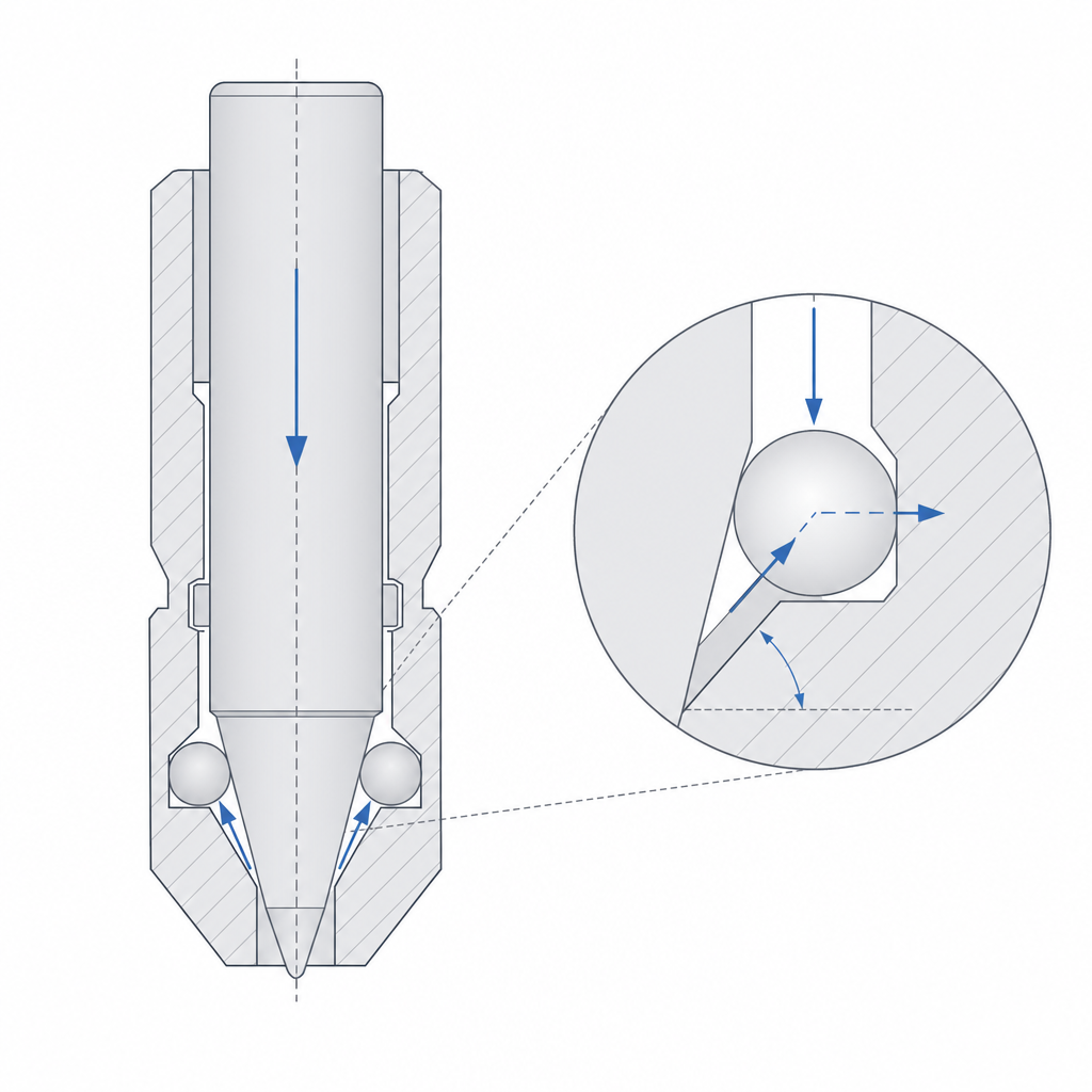
Nothing pushes the balls radially outward directly: the spring pushes axially, along the pin, and the balls move radially, perpendicular to it. What turns one into the other is a wedge. The shoulder of the plunger — the conical transition between the fat diameter and the thin one — slides under the balls when the spring drives it toward the tip, and lifts them. It's the same principle as an inclined plane: a force along the ramp resolves into a normal component that pushes the ball outward.
The angle of that ramp is the design parameter that rules the most, and it drives two opposing behaviors at once. Fix the convention first and everything else follows: call the cone's angle, measured from the plunger's axis, α. When you try to pull the pin out with the balls proud, the edge of the hole pushes them inward, and the ramp relays that force to the plunger, trying to overcome the spring. With a shallow cone (small α, the ramp nearly parallel to the axis), the component that ends up pushing the plunger is small: the pin holds a lot of axial load before it moves. With a steep cone (large α, the ramp closer to perpendicular to the axis), the balls push the plunger easily and the pin releases under little axial force — to the point of letting go on its own under the service load. The ramp is, in practice, what separates a pin that retains from one that opens when it shouldn't.
And there's a threshold worth knowing, because it's the heart of the fastener. Below a certain angle the mechanism is self-locking: the friction between ball and ramp is enough that no pure axial load can retract the plunger, and the pin opens only by pressing the button. The threshold sits, roughly, where tan α equals the friction coefficient of the ball-ramp pair: below it, self-locking; above it, the spring starts to take part in the release threshold. That's why a well-designed commercial pin doesn't let go under load no matter how hard you pull: it works in the self-locking regime, and the load it holds is limited by the strength of the materials at the contact, not by the wedge's force balance.
Why plastic alone isn't enough
Almost the whole body of the pin is printable: a cylinder with a through bore for the plunger and two radial bores for the balls. The trouble lies exactly in the feature that defines the fastener, the ball capture. For the ball not to fall out, the mouth of the radial bore has to narrow in front of it: an inverted conical lip, on the side face of the cylinder, over a small hole. It's one of those geometries FDM can't resolve on its own — a severe overhang you can't orient without it collapsing — so the ball capture rarely comes off the slicer cleanly: the usual approach is to print the mouth open and then close it by staking or hot-deforming it, trap the ball with a metal ring or end ferrule, or assemble the balls from the inside with a separate piece that closes the pocket. Anyone claiming the body is "perfectly printable" hasn't looked at that lip.
And here the other limit of FDM in this mechanism shows up: contact pressure. When a steel ball bears against the edge of the bore and holds the axial load, it doesn't spread that load over an area: it concentrates it into nearly a line of contact between sphere and edge. That point pressure is enormous, and the plastic — which is soft and, on top of that, flows slowly under sustained load — yields. The mouth of the radial bore rounds over and opens under the hammering of each insertion, the balls pop out less and less, and there comes a point where they no longer bear enough and the pin lets go under a load it used to hold. On the plunger cone the failure mode is different and more insidious: the steel ball doesn't wear the plastic away, it indents it — brinelling — driving a dent into the ramp, and that dent becomes a pit where the ball settles and stops riding up the wedge when it's meant to pop out. The plunger snags in its own dent. It isn't a friction or lubrication problem; it's creep and indentation under repeated static load, and what matters against it is the yield strength and surface hardness of the material taking the point. That's why a ball-lock pin meant to do real work combines the printed part with metal components in the contact zones — the plunger, or at least the cone and the bore mouths; the plastic acts as body and guide, but it shouldn't be what takes the point contact of the balls.
Clearances: pop out just enough, slide smooth
The whole mechanism plays out in a few tenths, in different places that pull in opposite directions. The first is the ball protrusion: how far it stands proud of the body's diameter. It's the most direct safety parameter of the fastener, because retention depends not only on the cone angle but on which edge the ball bears against. A receiving hole with a sharp edge retains far more than one with a broken mouth: if the hole you push the pin into is chamfered or rounded, that edge acts as a ramp that "rides up" the ball and pushes it inward, releasing the pin under considerably less axial load. Size the protrusion for the worst edge the pin will meet, not for an ideal sharp corner.
The second adjustment is the radial bore for the balls. It has to capture the ball — narrow the mouth just enough that it won't come out when the plunger pushes it — while letting it pop out enough to bear reliably, and retract without binding when the plunger moves away. If the mouth grips too hard, the ball drags as it moves and the button presses with difficulty; if it grips too little, the ball falls out and you lose the pin. It's an adjustment with little margin, made worse by what you already know about printed holes: a radial bore comes out oval and narrower than you drew it, and all the more so the further you leave it overhanging. Tolerances for moving parts works this through, and here it counts double because the bore retains a sphere, not a cylindrical shaft.
The third adjustment is the plunger inside its pocket. It has to slide smooth along the whole stroke, with no play that would let it wander and misalign the wedge, but with no grip that would jam it mid-stroke and leave the balls half-out. It's a clean sliding clearance over a long travel, exactly the kind of fit that comes out best by keeping the plunger at size and opening up the pocket. The combination is demanding: three tight fits in one part where every tenth counts toward the assembly locking and releasing repeatably.
Sharing the load: one ball, two, or three
The draft always assumes two opposed balls, but the count is a design decision that lands right on the failure mode dominating this mechanism. A single-ball pin is the simplest, but it concentrates all the axial load at one contact point and loads the plunger sideways against the wall of its pocket. Two opposed balls balance that side thrust and split the load across two points. Three balls at 120° split it across three and center the plunger better. Since the real limit of the printed fastener is point pressure on the plastic, sharing the load across more balls lowers the pressure at each contact and pushes back both the rounding of the mouth and the indentation of the cone: if you're going to take the contact to metal only in part, more bearing points buy you margin.
When it's the right fastener and how it fails
The ball-lock pin shines where you want to assemble and disassemble many times, by hand, without tools, and hold axial load in between: removable shafts, quick-change fixtures, accessories taken on and off daily. Against a plain pin that backs out on its own or a thread that takes a while to undo, the ball-lock gives a firm click, retains for real, and releases with your thumb. That's exactly its reason for being.
Its failure modes are the ones we've been naming, and it pays to have them together so you can design against them. The first is the rounding of the mouth and the indentation of the cone under the point pressure of the balls: the bore mouths open up cycle after cycle and the cone gets pitted by the ball's dent, and in both cases the pin loses retention; that's the underlying reason to take those zones to metal and to share the load across several balls. The second is jamming from debris: the mechanism has fine gaps where the plunger runs and the balls move, and a bit of dust or a stray print string is enough to leave the button stuck pressed or the balls not popping out. The third is unintended release: if you work above the self-locking threshold with a weak spring, or worse, with too steep a ramp, the service load pushes the balls inward, overcomes the spring through the wedge, and the pin lets go when it shouldn't — the most dangerous failure, because it seems to lock until it gives. Design it with the cone in the self-locking regime, the spring sized to keep the balls proud, the contact zones in metal, and the fits measured on your own printer, and you'll have a fastener that survives the cycles you're going to ask of it.
Since almost everything in a ball-lock pin is decided at the contact between the steel sphere and the plastic, and that contact is point pressure on a printed wall, the natural next step is to understand what FDM does to a hole that has to retain: Tolerances for moving parts takes you from the nominal on screen to the real cavity that comes off the bed.