Rivets, barbs, and staking
Some joints you never want to open again. Think of the two halves of an enclosure sealed at the factory, a panel that closes off a compartment, a structural label riveted to a frame. For those, you don't need screws, inserts, or threads printed to fit: you need a fastener that goes in easily from one side and, once inside, physically refuses to come back out. This is the family of one-way joints, and in FDM they come nearly for free, because the printed part itself acts as the rivet.
Why one-way changes everything
Both a thread and a releasable snap-fit give up part of their design to being able to undo themselves: an exit ramp, a radius that lets the tab flex back, a clearance that lets a tool through. A permanent fastener doesn't pay that tax. Its entire geometry is devoted to one thing: bending just enough to cross an edge and then bearing against it the other way.
Two advantages follow from that. The retention force can be far greater than the insertion force, because the angle of the face that bears from behind can be nearly square while the entry ramp stays gentle. And there's no hardware: the cost in filament is negligible next to a screw and its nut.
The price is total permanence. We state it now and repeat it at the end, because it's the most expensive mistake on this page: if you're ever going to need to open the joint, this is not what you want.
The push rivet: a body the pin forces open
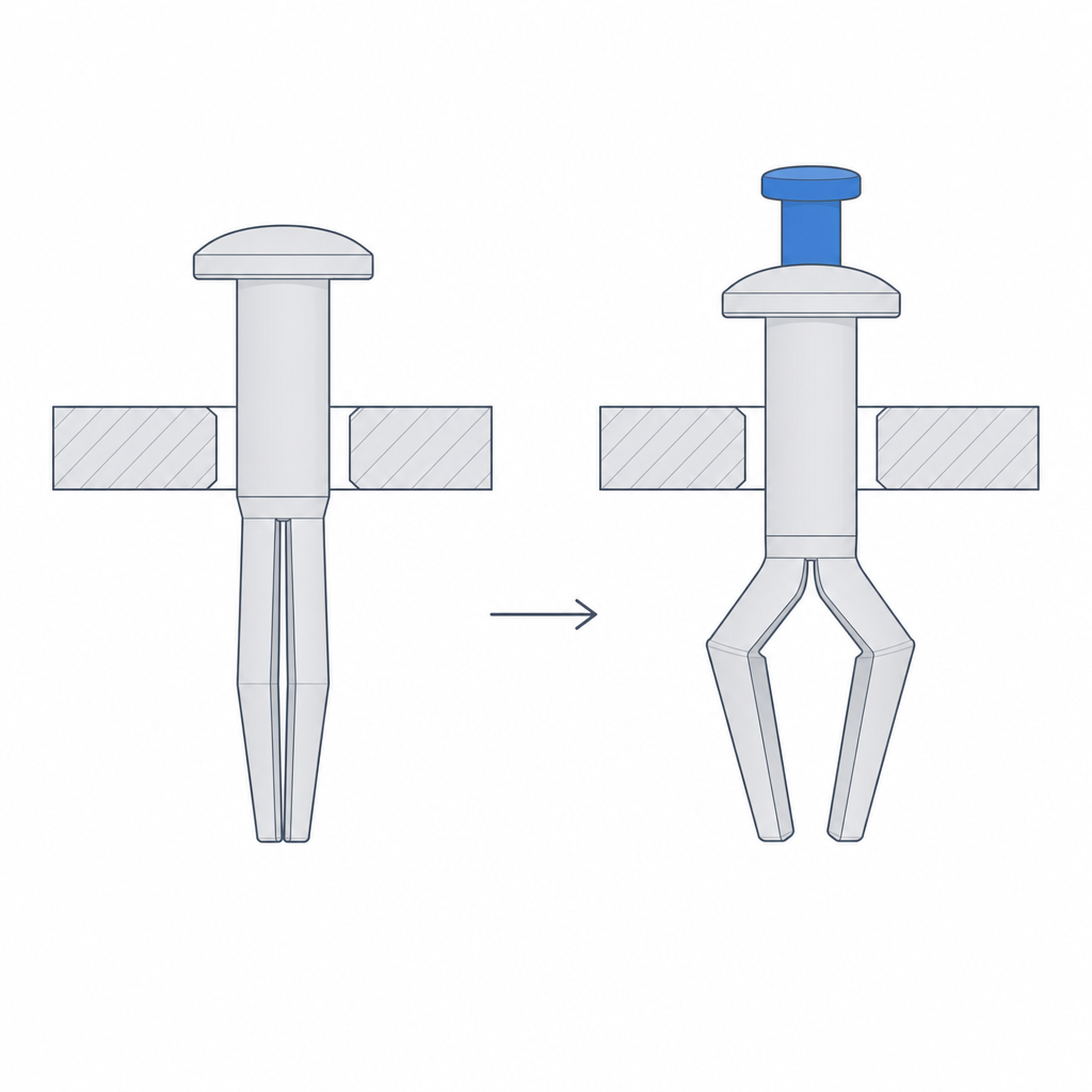
The push rivet is made of two pieces: a split body—divided lengthwise into two or more legs—that passes through a clearance hole in both parts, and a central pin you insert afterward. At rest, the printed legs sit open at the nominal diameter; to cross the hole you actively close them against its chamfer, and that elastic flex is the delicate moment: if the legs have little clearance or an unfilleted base, that's where they crack along the layer line. Once inside, you push the pin all the way down: it fills the central cavity and forces the legs back open. They are now locked in their expanded position, bearing behind the hole with no room to fold back. The top flange bears against the opposite face and the assembly is trapped between the flange and the open legs.
The physical trick is that retention depends on neither friction nor a tight fit, both of which are unreliable in FDM. It depends on geometry: once the pin is inside, to pull the rivet out you'd have to close the legs, and the pin prevents that. That's why it holds against tension even if your hole ended up a little wider than nominal—but only a little. If the hole grows too much, the open legs overlap the edge by less; past a certain point the overlap is lost and the rivet pulls out as if the legs had never locked.
Size it for the total stack thickness it must join: the body must be long enough for the legs to emerge fully past the opposite face, because if they end up halfway through the hole they bear against the chamfer and slide back out. Leave clearance between body and hole too: the rivet crosses with the legs closed, not press-fit.
Barbs: one-way teeth on a pin
The barbed pin takes the same one-way idea to its purest form. Instead of legs that expand, it has a series of angled teeth along the shaft, all pointing backward like those on a Christmas-tree fastener. Each tooth has a gentle ramp on its front face and a back face nearly perpendicular to the axis. As you push, each barb bends inward when it rubs the edge of the hole, springs back; its rear face then catches against the material and won't let it retreat.
The design hinges on how much each barb bends as it passes. That flex has to stay below the material's limit, or the tooth cracks or shears at the entry instead of snapping cleanly. A barb too tall for the hole diameter, or with a sharp, unfilleted base, concentrates so much stress at the root that it breaks on the first insertion. A barb too short grips little and pulls out. The sweet spot is for each tooth to flex just enough to cross and recover its shape on the other side without ever having exceeded its elastic deformation.
In FDM, what decides whether a barb flexes or breaks is its orientation relative to the layers. A barb printed with the layer line parallel to the direction it has to bend will shear along that seam before it flexes: this is anisotropy at work. Orient the part so the tooth works across the layers, not along them, just as you'll do with the heat-staking post below.
You have one comfortable design parameter: the number of barbs. More staggered teeth spread the retention across several points and make you less sensitive to the part's exact thickness—something always catches—but they also add insertion force and multiply the chances that one shears on the way in. For PLA, which is stiff and unforgiving of flex, use fewer teeth and a larger root radius. A more ductile material like PETG or TPU tolerates more aggressive barbs: these flex without cracking — the same principle of staying below the deformation limit that governs press fits in Interference without cracking.
Staking: deforming the printed plastic itself
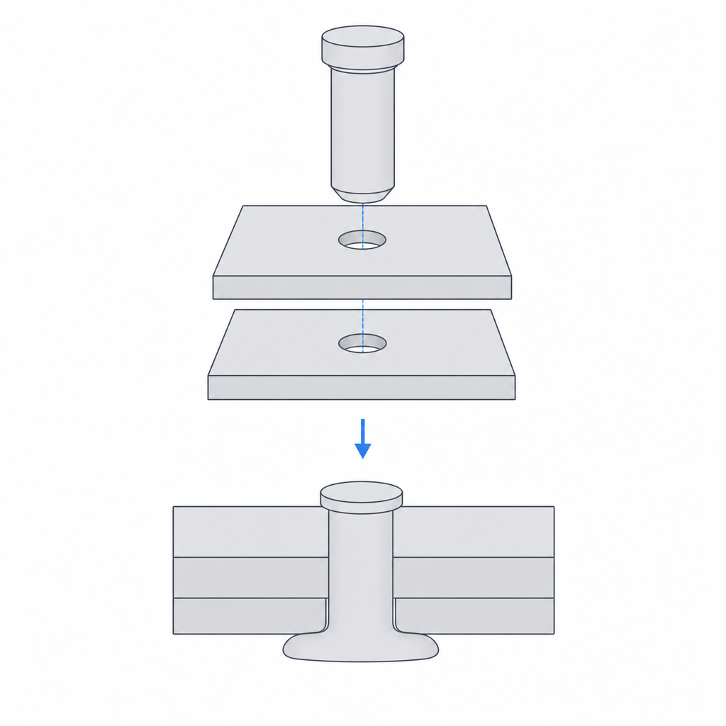
Heat staking inverts the previous principle. In a rivet or a barb, the fastener goes in already at its final shape and bends elastically along the way. In staking you print a solid post—a plain cylinder standing proud of one part—pass it through the hole in the other part, and then, with a hot tip, melt and flatten the protruding end into a mushroom-shaped head. That head, wider than the hole, traps the second part against the base of the post. Nothing can pull back through the hole: the plastic has been re-formed hot and solidified on cooling into a new shape.
It's exactly the heat-set insert in reverse. In an insert, heat softens the plastic of your part so a metal sleeve can sink into it. Here the heat softens the printed plastic —the post— so it's the one that deforms and embraces the other part. In both cases the trick is the same: bring the material above its softening temperature exactly where you want it to flow, and let it solidify in the geometry you've imposed.
The head is solid and depends on no printed clearance, so it resists pull-out well: a slightly oversized hole won't defeat it, nor will the gradual loosening a barb suffers. Its weak point isn't breaking under pure tension, but the interface between the melted head and the printed post: there the re-melted material sits on top of the post's layers and, if forced, the head shears or peels along that seam. It isn't the indestructible joint it first appears to be, but it is the hardest to reverse without a tool.
Sizing the post
All the strength of staking lives in the head, and the head is formed from the material left standing proud of the part. If you leave too little post protruding, the head comes out thin, never reaches over the edge of the hole, and tears free under load; if you leave too much, the material overflows the sides and the head ends up uneven.
As a starting point, let the post stand proud of the hole by 1.5 to 2 times its own diameter. That excess volume is what the hot tip redistributes into the head, and it should roughly match the volume of the finished head: with that proportion you get a dome that overlaps the hole, not a flat smear. You match the post diameter to the hole in the other part, with just enough clearance to enter without forcing: you don't want interference here, the hole only guides the post until the head locks it.
The tip matters as much as the volume. A flat, smooth tip won't form a clean mushroom head: it pushes the material out to the sides unevenly, and that's the overflow you want to avoid. Use a tip with a conical or hemispherical cavity—bell-shaped—that gathers the molten material and forms it into a dome. And work with the temperature well above the material's softening point, not barely above it: the tip has to melt the end in that brief contact, not just warm it.
| Parameter | Guide value | Why |
|---|---|---|
| Post diameter | matched to the hole, slight clearance | enters without forcing; retention comes from the head |
| Height proud of the part | 1.5 to 2 times the post diameter | supplies the volume to form an overlapping head |
| Final head diameter | ≈ 1.5 times the post diameter | overlaps the edge of the hole all around |
| Tip shape | conical or hemispherical cavity | forms a dome; a flat tip overflows |
| Tip temperature | well above the softening point (≈ 180–210 °C for PLA, 230–250 °C for PETG, 240–260 °C for ABS) | the plastic must flow within seconds, not merely warm |
The one rule worth repeating
We flagged it at the start and here it closes: all three fasteners share one virtue and one catch. The rivet locks its legs, the pin catches its teeth, and staking forms its head; none has a return path by design. That's why they're cheap, strong, and free of hardware, and that's exactly why opening the joint means breaking it. Decide it before you print, not after: if you're ever going to need access —swapping a battery, replacing a board, reopening an enclosure—, switch to another family and design a tab with an exit ramp in Snap-fits that won't release.