Helical and herringbone gears: angled teeth, smooth and quiet
A spur gear transmits in jolts. Each tooth comes into contact all at once, with its entire flank engaging simultaneously, takes up its load, and disengages; the next one repeats the cycle, and that succession of impacts is what you hear humming and what hammers the tooth root turn after turn. The angled tooth trades that abrupt entry for one that starts at a corner and sweeps diagonally until the whole flank is engaged. It meshes progressively, and from that single change come its three advantages: more smoothness, less noise, and more load. And also the problem you came here to solve: a new force that pushes along the axis and that, if you don't plan for it, will pull your mechanism apart.
The tooth enters on a diagonal, not all at once
In a spur gear the line of contact is parallel to the axis: the tooth engages across its full width at the same time. The contact ratio — how many pairs of teeth are transmitting at once — rises and falls in steps, and at the instant a pair enters or leaves there is an abrupt change in stiffness that translates into vibration and noise. That is the spur gear's acoustic signature: a hum at the tooth-passing frequency.
When you tilt the tooth by a helix angle, the line of contact stops being parallel to the axis and crosses the flank diagonally. The mesh no longer starts all at once: it begins at one end of the tooth and advances progressively toward the other as the gear turns. That means one tooth is still entering while the previous one has not yet left, so at every moment there is more length of contact spreading the load. The contact ratio goes up and, above all, varies continuously instead of discontinuously. Fewer jumps in stiffness means less vibratory excitation: hence the smooth, quiet running. And hence too that the same module can carry more torque, because that torque is shared among more teeth in simultaneous contact and along a longer, angled line of contact, instead of being dumped all at once onto the flank of a single tooth entering cold.
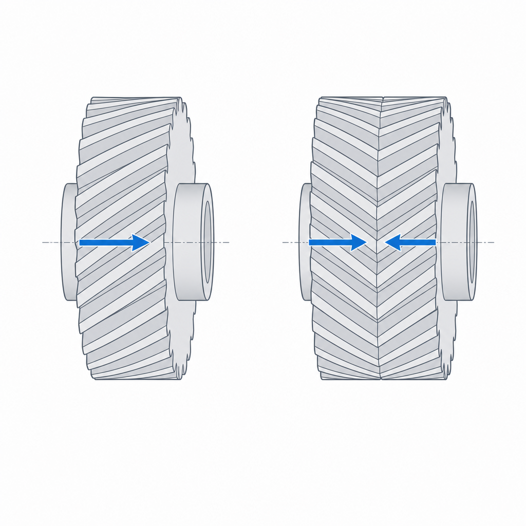
The trade-off is physical and there is no dodging it: tilting less reduces the thrust, but also reduces the effect you were after. That same diagonal that spreads the load also splits it in two. The force between teeth now has a tangential component, the one that turns the wheel, and an axial component, which pushes the wheel along its own axis. The larger the helix angle, the smoother the mesh, and the larger the axial thrust. A plain helical gear always pushes toward the same side of the axis while it transmits.
Axial thrust is the failure mode you don't see coming
That thrust is no academic subtlety. In a metal drive it is absorbed by a thrust bearing or a shoulder against which the wheel bears. In a printed part that didn't plan for it, the plain helical wheel simply walks along its axis until something stops it: the wall of a housing, a stop that wasn't meant for continuous load, or the end of the shaft itself. And meanwhile the contact between teeth goes off-center, the mesh loses the contact ratio you cared so much about, and the running turns rough — exactly the opposite of what you were after.
That is why, if you print a plain helical gear, you have to design the axial stop as part of the mechanism, not as an add-on. You need a surface for the wheel to bear flat against, ideally a low-friction washer or a generous shoulder, knowing that this contact is going to rub permanently and will wear. Plastic against plastic under continuous axial load is exactly the combination that ages worst: creep, wear, and growing play.
The herringbone cancels the thrust by combining two opposing helices
The herringbone — double helix, two halves in a V — solves the axial thrust by geometry, without paying for it with a bearing. The idea is straightforward: if a right-hand helix pushes the wheel to one side, a left-hand helix of equal angle on the same wheel pushes to the other with the same force. You place both on the same wheel, side by side forming a V, and the two axial components cancel in the resultant on the shaft. You keep all the smoothness of the progressive mesh and zero net thrust along the axis.
It pays to be precise about that "cancel": they don't disappear locally. In each half the axial force still exists and travels through the body of the tooth toward the center; what cancels is the resultant on the wheel. The practical consequence is that the central apex stays loaded: the two halves push against each other and an internal stress concentrates there that does not worry anyone in metal, but that in a printed part points straight at its weak plane. We'll come back to it when we talk about how it fails.
This is what makes the herringbone such a fitting part for FDM. In metal the double helix is expensive to machine — you have to cut two opposing helices and sometimes leave a central groove for the tool to run out — and that is why historically it was a drive solution reserved for demanding applications. Printed, the geometric complexity costs you nothing extra: the machine lays down the V as easily as a single helix, and since there is no tool to clear, you don't need the central groove. You can make the V continuous, with no slot, which along the way avoids the stress concentrator that groove would introduce. You eliminate the axial thrust with no bearing, no rubbing stop, and no wear surface to keep an eye on. For a printed drive that has to last, that absence of net axial load is one worry less.
Why the V prints clean
This presumes an orientation, and it's worth stating it before going on: the wheel is printed standing up, with its axis vertical on the bed. Everything that follows — the helix as accumulated rotation, the strong plane, the direction of the load — only holds in that orientation. Laid down, with the axis horizontal, the layers cut across the tooth and the root is left weak between layers, which is exactly the failure mode you most want to avoid in a gear.
Standing up, the tilt of the tooth is not an overhang that has to be supported: it is a gentle twist of the profile layer by layer. Each layer lays down the tooth contour slightly rotated relative to the previous one, and that rotation accumulated over the height is the helix. Since the typical angle is modest, the rotation per layer is minimal and the flank rarely poses an overhang problem. The result is a continuous flank surface and, what matters most in FDM, the tooth works in the strong XY plane: the mesh load runs along the beads, not between layers. The interlayer weakness, the trap of so many functional printed parts, here ends up aligned in the good direction — as developed in Layer orientation for motion.
Both the plain helical and the herringbone print well standing up, and in neither one is the flank overhang usually the limiting factor. The real difference is not in some magical self-support of the apex, but in what the continuity of the twist demands: if the layers go out of alignment — through poor adhesion, through excessive speed at the corners, through unstable temperature — the helix stops being continuous, the progressive contact breaks, and you lose the smoothness that was the whole reason for tilting the tooth. That continuity is what you have to protect, and it is the same in both profiles.
Clearances: backlash and helix angle have to match
A helical or herringbone gear needs the same backlash as a spur one: a deliberate gap between the flank that pushes and the opposite flank of the meshing tooth, so the two wheels don't seize when the printer leaves the teeth a little thicker than drawn. Remember that a printed hole comes out narrow and a boss comes out thick; a tooth is a boss, and two meshing teeth add up the overthickness of both flanks. In an angled profile that gap is measured in the plane normal to the tooth, not the transverse one, but the principle doesn't change. Without backlash, the drive runs tight, rubs continuously, and heats up; the method for setting that gap from your real printer is the same as for any fit and you have it in Tolerances for moving parts.
But here there is a condition that the spur gear doesn't impose on you quite so sharply. For two wheels to mesh they have to share three things: the normal module, the normal pressure angle, and the helix angle. The module and the pressure angle you almost always take for granted by using the same tooth profile; the helix angle is the one that slips through. A 20° pinion meshes with a 20° gear, not a 15° one: if the angles don't match, the diagonal contact that promised to spread the load shrinks to a line or a point, and instead of a smooth mesh you have one that bites at a corner and punishes that zone.
And alongside the angle comes the hand. In a pair of parallel shafts, the two wheels must carry helices of opposite hand: a right-hand one meshes with a left-hand one. (In shafts crossed at 90° the hand relationship changes and both usually run the same hand; that's a different setup.) In a herringbone the requirement doubles: the two V halves of each wheel have to be exact mirror images for the axial-thrust cancellation to be clean. If one half comes out with a different angle from the other, the thrust doesn't fully cancel and a residual force reappears along the axis — exactly the one the geometry was meant to eliminate.
| Aspect | Plain helical | Herringbone (double helix) |
|---|---|---|
| Net axial thrust | Yes, continuous; needs an axial stop | Canceled by the two opposing helices |
| Internal load | Low | High at the apex; watch for delamination |
| Smoothness and quietness | High | High |
| Geometric complexity | Medium | Higher, but free when printing |
| Central groove | Not applicable | Unnecessary in FDM: continuous V |
| Assembly requirement | Axial stop or thrust bearing | Radial support only |
The layer-to-layer consistency of the angle is, in practice, as critical as the backlash: the progressive mesh only exists if the helix is continuous from the first layer to the last. A loose calibration that on a spur gear would only give you a bit of play, on an angled one degrades the diagonal contact and, on a herringbone, reintroduces the axial thrust that the geometry was meant to cancel.
When it's worth it and how it fails
Move from spur to helical or herringbone when the noise bothers you, when you need more load capacity from the same module, or when you want to eliminate the tooth-entry knock in a drive that has to run smooth. Between the two, choose the herringbone whenever you don't want to deal with the axial thrust — which in a printed part is almost always the case —: it gives you the fine running without forcing you to design and maintain a stop surface that wears. Save the plain helical for when the width is so tight that the V won't fit, or when you already have a robust axial support for some other reason.
There are four failure modes and it's worth having them identified. The first is the unsupported axial thrust in the plain helical, which we've already seen: with no stop, the wheel drifts and the mesh goes off-center. The second belongs to manufacturing: poorly aligned layers that break the continuity of the angled tooth, turning the promised helix into a staircase and ruining the progressive contact — and, in a herringbone, the thrust balance. The third is the one for any printed gear, angled or not: tooth breakage at the root if the module is too small. Tilting the tooth spreads the load better, but it doesn't manufacture strength where there is none; a module too small for the torque you're asking will break the tooth all the same, just more quietly.
The fourth is specific to the printed herringbone, and it's born of that internal load at the apex. The axial components of the two halves converge on the center line and load it permanently; printed standing up, that zone coincides with a bonding plane between layers. Under high torque and over time, the apex can delaminate, splitting between layers right where the two halves push. It is the failure most characteristic of "herringbone plus FDM" and you fight it the same way as any interlayer weakness: raise the extrusion a few degrees, lower the speed across that central band, and don't ask a continuous apex for more torque than its interlayer weld can hold.
Before you tilt anything, then, make sure the equivalent spur tooth would already have module to spare for the load, and treat the helix for what it is: an improvement in smoothness and load sharing, not a substitute for the section the torque demands. The orientation that makes the tooth strong is the same one that protects the apex, and it's developed in Layer orientation for motion.