Smooth one-way drive: sprag, roller-ramp, and cable clamp
A ratchet no-back works, but it has two flaws you can hear and feel: it clicks as it advances, and when you load it in reverse it backs up by one tooth of play before it bites. That angular slop is sometimes unacceptable — in a precision winch, a descent brake, a mechanism that has to hold exactly where you left it. The family that solves this has no teeth: it locks by wedging asymmetric elements or rollers against a tapered ramp. It engages in any position, with no discrete step, no click, and no angular play. It is the most elegant one-way mechanism, and in FDM it is also the hardest to print well. It is worth understanding why it locks before you start fighting the tolerances.
The wedge that tightens itself
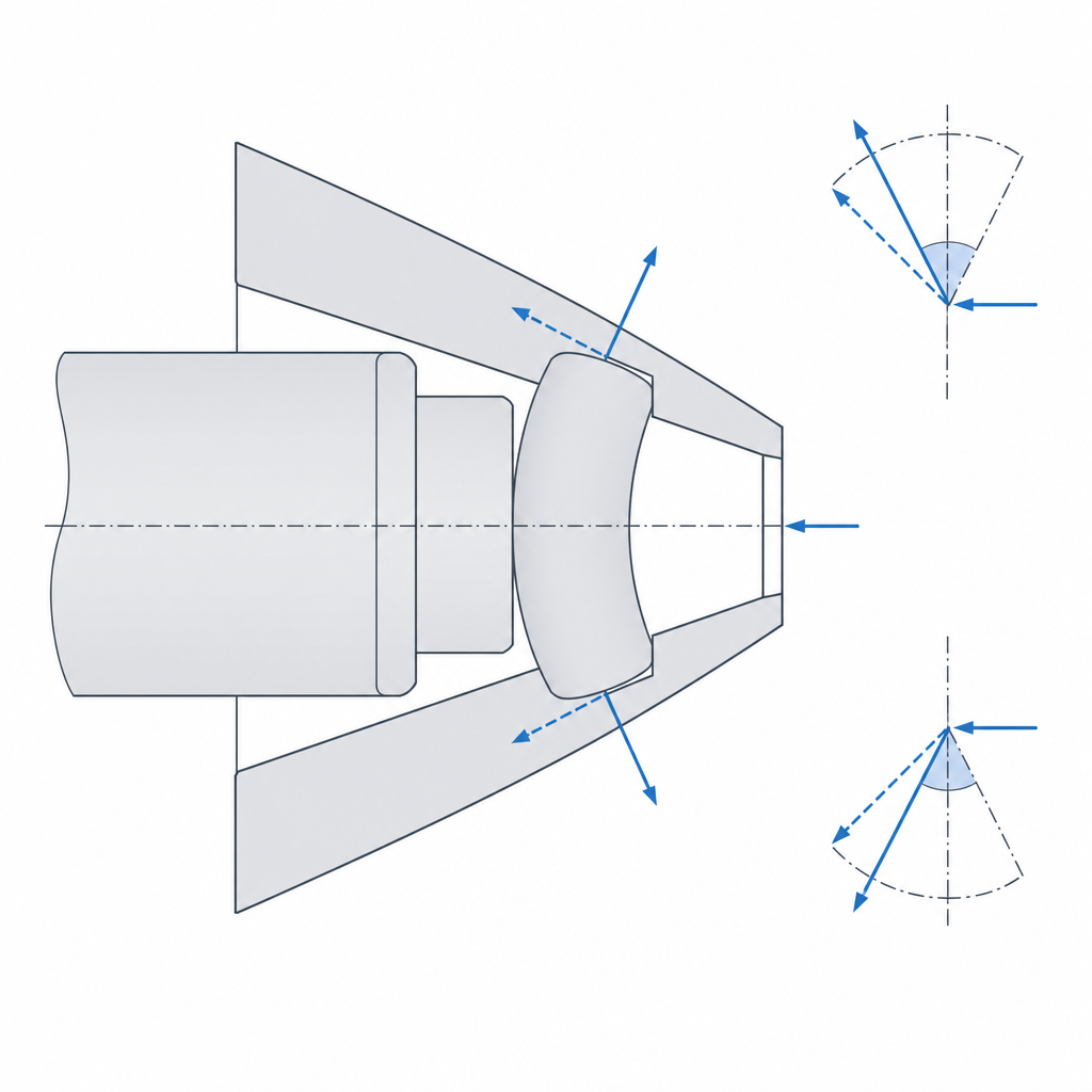
The idea is to replace a tooth's positive engagement with a friction grip that tightens itself under load. Picture a roller sitting in the wedge-shaped gap between an inner shaft and an outer race: on one side the gap is wide and the roller rolls free; on the other it narrows to a tight angle. When the assembly tends to turn in the locking direction, the roller is dragged toward the narrow part of the wedge and gets trapped between the two surfaces. A sprag does the same thing by tilting: it is an asymmetric element, with two different radii at its ends, mounted between the two races. As it tips, its effective radial dimension — the span between the faces that contact the two races — grows beyond the gap, and it wedges.
What makes this grip special is that it feeds back. When the roller wedges, the load pushes it harder toward the narrow zone; that force resolves into a normal component that presses the roller against both races, and the friction that holds the assembly is proportional to that normal force. More locking torque, more normal force; more normal force, more friction; more friction, more torque held. The loop closes in an instant: there is no lost motion and no angular step to travel through. That is why the grip is practically continuous and happens in any position, not in discrete steps of so many degrees, as in a ratchet.
The price of that self-amplification is that locking depends entirely on the ramp angle and the friction of the surfaces. For the roller to wedge instead of slip, the half-angle of the wedge has to stay below the friction cone. And here is a subtlety worth pausing on: in a roller no-back there are two contacts, the roller against the inner shaft and the roller against the outer race, each with its own coefficient of friction. The wedging condition is that the half-angle not exceed the sum of the two friction angles. In a printed version those two contacts can have very different friction — an embedded metal shaft against a plastic race — and that changes the arithmetic. Almost everything that makes it hard to print lives in that one condition: the angle staying below the friction cone.
Why it beats the ratchet (and the friction spring)
Against a ratchet, the advantage is threefold. First, there is no discrete step: the roller or the sprag engages in a continuous position, so you hold exactly where you release, without backing up by a tooth's width. Second, there is no click: locking is silent because there is no tooth jumping over another against a spring. Third, there is no angular play on load reversal — a well-made ratchet always has some clearance between tooth and pocket, and a roller no-back has none.
Against a friction-spring brake—a wrap spring squeezing a shaft—the difference is the stiffness of the grip. A spring holds up to a certain torque and beyond that slips gradually; wedging, as long as the ramp stays inside the friction cone, does not slip progressively: it grips with no angular play up to its torque limit, and at that point it lets go all at once. That is why you pick it when neither the ratchet's click nor the spring's progressive slip is acceptable: precision no-backs with no angular play, descent safety brakes, indexers that cannot back up.
The same principle carries over to a cable with the cable clamp (rope grab). Instead of two circular races, an eccentric cam with a toothed or knurled surface pivots against a fixed anvil, and the cable runs between the two. Pulling in the free direction barely disturbs the cam and lets the cable run; pulling in the locking direction turns it toward the cable, the wedge closes and it bites the cable against the anvil. It is the same self-amplification—more tension, more bite—applied to a strap or a cable instead of a shaft, and it is what is inside an ascent locker or a load tensioner.
Printing it in FDM: the most demanding of the no-backs
Here theory collides with the reality of FDM. The whole operation rests on two things FDM is bad at: fine ramp angles and consistent friction surfaces. The ramp that wedges the roller is a wedge of a few degrees, and a few tenths of dimensional error or a slightly oval race are enough to shift the effective angle. But the friction problem is not the one it seems: plastic has a high coefficient of friction—its friction cone is wider than steel's, not narrower—so in principle it is more forgiving. What makes it treacherous is that the coefficient is unstable: it changes with the orientation of the beads, with the layer finish, and with the wear of the first cycles. The cone is not narrow — the problem is that it shifts on you.
There is also an effect that always works against you. Under load, the roller indents the plastic race: the contact patch grows and the local ramp flattens, so the effective angle opens up exactly in the direction that takes you out of the friction cone. The elastic deformation of the plastic pushes the system toward slipping, not toward locking. This is a basic physical reason why a fully printed wedge no-back is always marginal.
The practical conclusion is that a high-performance no-back is rarely all plastic. Before you give in to metal there is an intermediate step: if the race is printed, choose a material that can take the friction and wear duty. A PA (nylon), a PC, or a carbon-fiber-reinforced filament give a higher yield strength and better wear behavior than PLA or PETG, and a self-lubricating pair—nylon against a metal shaft—is the sensible choice when one of the two races is plastic. The next step, if you need real performance, is to embed the components that do the friction work: calibrated metal rollers and their springs, housed in a printed cage that only positions them. Those commercial rollers bring the finish and hardness that a printed ring cannot, and leave your printed part responsible only for the geometry. Planning the housings, the insertion tolerances, and the assembly direction is the same problem as fitting any other metal component inside a printed part, which Interference without cracking develops.
If the ramp race is printed, treat it as a working surface: nearly solid wall under the contact zone, generous perimeters, and the best layer finish you can manage, because the contact pressure at the wedging point is very high and is concentrated along a line. The roller-race contact is always compressive, but the force that reacts the torque—the hoop tension of the ring that surrounds the races—can pull layers apart. Orient the part so that hoop stress works in the plane of the layers, not perpendicular to them: a ring whose locking force tends to separate two layers delaminates, and the same ring oriented so that stress follows the beads resists considerably more.
The failure modes: why almost all of them are in the ramp
There are three ways to fail, and each is fixed in a different place — it is worth learning to tell them apart.
The first mode is slipping: the mechanism doesn't wedge and lets the load back up. The cause is almost always a ramp that is too shallow—the angle falls outside the friction cone—or already worn surfaces, which drop the friction below what the ramp needs. The robust remedy is to close the wedge angle, not add a spring: the spring only repositions the roller, it is not what holds the load. Roughening the race does raise the friction, but it is a double-edged patch: it accelerates wear and crushing, and makes the coefficient even more unstable during break-in—exactly what the previous note advises against.
The second mode is the opposite, and it is treacherous because it looks like success: permanent grip. If the wedge is too aggressive—angle too tight, too much interference—the roller wedges with so much force that it doesn't release when you reverse the turn, and the no-back becomes a fixed lock in both directions. The self-amplification that worked in your favor now works against you: the harder you pull to release, the tighter it grips. The boundary between "grips firmly" and "never lets go" is narrow, and it is the reason to prototype with adjustable clearance.
The third mode is wear: the crushing of the plastic races under the contact pressure of wedging. The whole locking force concentrates on the line where the roller touches the ramp, and the plastic, with its low modulus and yield strength, creeps and dents under that repeated load. With each cycle the footprint grows, the effective angle opens toward slipping, and the grip degrades. That same contact pressure puts the wall in tension, so everything you know about avoiding cracks under concentrated load—a wall with enough section, force spread out, no sharp edges—applies here; see Interference without cracking.
There is also a design lever that is not a failure mode but conditions all three: the number of elements. A single roller concentrates all the contact pressure on one line; spreading the load across several distributed sprags or rollers lowers the pressure per contact and makes viable a torque that with a single element would crush the race on the first cycle. In FDM, where the race is the weak link, spreading is nearly mandatory.
| Decision | If you fall short | If you overdo it |
|---|---|---|
| Ramp angle | Shallow ramp: slips, doesn't wedge | Aggressive wedge: won't release in the free direction |
| Race friction | Worn or polished surface: slides | Very rough race: wears and crushes sooner |
| Repositioning spring | Weak: the roller locks late | Strong: drags and brakes the free direction |
| Number of elements | Few: high contact pressure; the race dents | Many: uneven sharing if the geometry isn't precise |
The free direction and what to expect from the printed version
A no-back has two behaviors, not one. In the locking direction it wedges; in the free direction, the roller has to release and roll. For that it carries a light spring that preloads the element just short of engagement, so that wedging is immediate and there is no lost motion before it bites. That spring neither holds the load nor rubs the ramp: it only eliminates the dead travel. If it is too strong, the assembly drags and squeaks in the free direction; if it is too weak, the roller doesn't reposition and the next engagement is late. The no-back spring is as much part of the design as the ramp.
Be realistic about what you ask of the part. A fully printed wedge no-back is a demonstration or low-load mechanism, not the plastic equivalent of a metal roller clutch. The contact pressure that wedging concentrates on the race far exceeds what PLA or PETG can take without denting, so the fully printed version is good for teaching the principle, for a low-torque mechanism, or for a prototype where you are only validating the geometry. For real load, the printed part is the cage and the structure, and the grip is done by embedded metal rollers and springs.
And prototype it with adjustable clearances from the very first attempt. You are not going to hit the wedge angle on the first try: print the ramp with a means of adjustment — an eccentric that rotates the ring, a screw that draws it in, swappable shims — and close it until it grips without sticking. Note the adjustment that works and turn it into a fixed dimension only once you have it. It is the same method as a tolerance tower, but on a mechanism where the target is a band a few tenths of a millimeter wide between two opposite failure modes. The clearance between the roller and the ramp decides whether it wedges or slips, and that clearance comes from measuring your printer, not from a catalog value; it is exactly the reasoning of Tolerances for moving parts, applied to a fit where the margin between "grips" and "slips" is a matter of tenths of a millimeter.
If that demand seems excessive for what you need, ask yourself whether you really need continuous grip. When a click and a tooth's worth of play are tolerable, a printed ratchet is far more robust and forgiving of errors. The smooth no-back is the tool for when that play won't fit—and for those cases, embedding the metal hardware detailed in Interference without cracking is what separates a mere demonstration from a mechanism that truly holds.