Sliding dovetail: male and female trapezoidal rail
A dovetail is the linear guide that needs no end caps, no retainers, not a single screw to keep the carriage from coming off: the shape itself traps it. A rail with an inverted-trapezoid cross-section—wide at the base, narrow at the top—drops into a groove of the same profile, and from that point on it can do exactly one thing: slide along. Pulling up, pulling sideways, or trying to tip it gets you nowhere, because the two angled flanks are in the way. It's beautifully economical in what it saves, and treacherous on a single number: the clearance between flanks. Get it right and you have a firm, play-free slide; miss it by a tenth and it either seizes halfway along its stroke or rattles side to side as if you'd never bothered with the dovetail at all.
Why the shape holds on its own
On paper, the kinematics are those of a body stripped of five of its six degrees of freedom, leaving one. A free solid in space can translate along three axes and rotate about three more; the dovetail cancels five of those six motions with pure geometry and keeps only translation along the rail. The trick is in the flanks: angled inward, the two of them form a pair of wedges that converge at the top. The carriage can't lift or shift sideways because either of those motions wedges one flank against the other; there's no way out except along the rail. Where a rectangular guide would need a top closure cap, the trapezoid's angle does the job. That's why a well-made dovetail holds in every direction without a single added part.
And I say "on paper" because the clearance you need for it to slide leaves some real play behind: with a gap between flanks, the carriage keeps a little pitch and yaw. The constraint is nominal, not perfect, and that's why tuning it is a fight between two evils—seizing or rattling—rather than a search for a single ideal point.
That angle is the first design decision, and it's a physical compromise, not an aesthetic one. The convention is to measure it from the base, and it pays to fix that before discussing anything else: a small angle—a very shallow flank, toward 30 degrees or less from the base—is the most retentive, because the wedge closes up tighter and presents more surface opposing any lift of the carriage. A large angle—a more vertical flank, approaching 60 degrees—retains less well but slides with less friction under load, because the wedge pinches less. And if you keep opening it toward 90 degrees you stop having a dovetail at all: the flank goes vertical, the wedge vanishes, and you're left with a straight groove that the carriage walks right out of by pulling up. For FDM, a comfortable range lives between 30 and 60 degrees from the base; closed when what you want is retention, open when what you want is smooth travel.
The clearance between flanks decides everything
The behavior of any sliding guide is settled in the gap between the rubbing surfaces, and in the dovetail it's worse: the contact is long and happens on two flanks at once. There's no single tuning point here as there is on a pivot; there are two inclined planes sliding in parallel along the whole rail, and the clearance counts per flank, not by the total width of the groove. If you draw the male and female to the same profile expecting it to run regardless, it won't: the printed walls close against one another and the carriage won't go in, or it goes in forced and gets stuck.
A reasonable starting value for a slide that runs firm and play-free is on the order of 0.15 to 0.2 mm per flank, tuned to your calibration. If you want it as a press fit—a module that goes in once and stays put—you take the gap toward zero or into interference; if you want it loose and free you can go up, at the cost of accepting some pitch. It's worth understanding why that gap is both critical and unforgiving. A dovetail's contact is extensive: the longer the rail, the more surface rubs and the more any excess tightness shows. A clearance that slides perfectly over a short span can seize on a long rail because the friction accumulates over the whole contact. And in the other direction, an overly generous clearance leaves lateral play: the carriage pitches between the flanks, rocks from one side to the other, and loses all the precision that justified choosing this guide. The margin between "seizes" and "rattles" is narrow: it fits in a single tenth.
The trapezoid's vertex seizes before the flank does
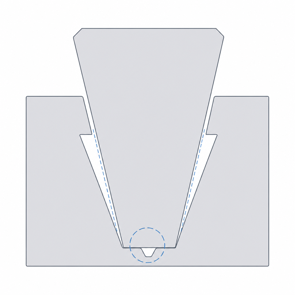
There's a cause of tightness that has nothing to do with the nominal flank clearance and that catches you off guard: the internal vertices of the trapezoid. Where a flank meets the bottom or the top face, the female leaves a concave corner and the male a convex one, and the printer never prints a clean miter there. The bead rounds the male's convex corner and leaves excess material in the female's concave one, so the two vertices clash before the flanks ever seat. The rail ends up resting on the corners, not on the faces that are actually supposed to slide, and it binds with a flank clearance that was correct on paper.
The fix is a relief at the vertex: a small fillet or, better, a relief groove in the female's concave corner that swallows the leftover material from the male's corner. With that gap, the flanks seat where they should and the clearance you calculated is the one that actually works. Add a lead-in chamfer at the mouth of the groove too: a short ramp that guides the carriage as it enters spreads out the first bite and keeps it from scraping right at the start, which is where starting the slide costs the most.
Long rails shrink and warp
There are failure modes that only show up when the rail gets long, and they come from cooling. Plastic shrinks as it cools roughly in proportion to length, so a long rail ends up a little shorter than the nominal you drew; and because the male and female have different mass and geometry, they don't shrink the same, and the fit you dialed in over a short span can come out tight or loose over a long one. On top of that comes warping: an elongated part tends to peel its ends off the bed and curl, and a curved rail no longer slides straight. It's not a flaw in your model; it's that the effective clearance is no longer uniform end to end.
The practical consequence is that a dovetail's clearance isn't tuned only as a function of the friction you want, but also of the length. For long rails it pays to open the gap per flank a little compared to a short span. You're counting on shrinkage and warping eating part of the margin, and on the accumulated friction biting harder. And before opening the gap, address the cause: good bed adhesion, a skirt or brim if needed, and a stable bed temperature are what keep a long rail straight. It's the difference between a guide that slides equally smoothly over its full length and one that goes in fine at one end and jams at the other.
Orient the print: lying down or standing up, and the trade-off
Orientation decides the quality of the two surfaces doing the work, and here there's a real compromise worth facing head-on instead of dodging.
The natural choice is to print the rail lying on the bed, with the sliding axis lying in the horizontal plane and the trapezoid profile growing in section as the part rises. That way the beads come out long and parallel to the motion, which is exactly what a surface that's going to slide wants. The price is geometric and you have to accept it: if the profile rises in Z, one of the angled flanks becomes an upward face and the other a downward overhang. That overhang, if the angle is aggressive, comes out sagging, rough, and out of spec, and a flank like that doesn't slide: it scrapes and wipes out the fit you calibrated. A moderate flank angle usually stays within what the printer holds without support; a very shallow flank may need you to orient the part so that flank presents as an ascending face, or a support that then degrades the finish.
The overhang-free alternative is to print it standing up, with the sliding axis vertical: then each layer is a flat trapezoidal section, with not a single flank hanging, and both faces come out clean. But you pay a different price: the sliding load now pulls between layers, which is the weak plane of an FDM part, and a tall rail standing up is more prone to warping and limits the length to what fits in height. No orientation is free. For long, moderately loaded rails, lying down with a flank angle that doesn't hang usually wins; when the angle is very closed or the part is short, standing up gives you flawless flanks in exchange for watching the load direction. That same reasoning of aligning the beads with the motion is what governs Layer orientation for motion.
| Parameter | Starting value | Why |
|---|---|---|
| Trapezoid angle | 30°–60° from the base | Small retains better, large slides more freely; toward 90° it loses retention |
| Clearance per flank (sliding) | 0.15–0.2 mm | The contact is double and long; calibrate it to your machine |
| Vertex relief | Fillet or relief groove | Leftover material at the corner binds before the flank does |
| Clearance on a long rail | High end of the range | Shrinkage and warping eat part of the gap |
| Orientation | Lying down if the flank doesn't hang; standing up if the angle is closed | Lying down gives aligned beads; standing up avoids the overhang at the cost of between-layer load |
When it's the right guide and when it isn't
The sliding dovetail shines as a moderate-load linear guide with no play: adjustable stops; clamping jaws; interchangeable modules that go in from one end and stay trapped without screws; slides that need to sit firm without pitching. And if you add a stop at the end of the travel, it stops being just a guide and becomes a fixed joint that only comes apart by drawing the carriage back out the way it went in. It is, in essence, the moving version of the woodworking joint: the same shape that in printed joinery fixes two parts together forever is here tuned so one slides over the other. That boundary between the fixed version and the sliding one is drawn by Printed joinery: dovetails and joints.
Where you don't want it is on very long spans with a tight fit, because the double-flank friction accumulates until it seizes; on loads that pull hard to separate the carriage from the rail, where a profile with positive retention behaves more predictably; and anywhere you need smoothness of slide above stiffness, because the extensive plastic-on-plastic contact will always rub more than a pair of short surfaces. The failure modes are the faces of the same badly tuned fit: friction seizing when the rail is long or the fit tight, vertices that clash before the flanks seat, lateral play when there's too much clearance, and rough flanks that scrape when the orientation left a face hanging. Get the angle right, split the gap per flank with length in mind, relieve the vertices, and seat it properly on the bed: with those decisions, the shape does the rest of the work on its own.