Press-fits that hold
The simplest permanent joint uses no screws and no glue: a shaft a little larger than its hole, forced in and held by friction alone. That's a press-fit. Sized right, it holds surprisingly well and takes seconds to design; sized wrong, it either backs out on the first try or splits the part as you assemble it. The difference between the two comes down to a few tenths of a millimeter and a couple of details almost nobody draws.
What actually holds a press-fit together
A press-fit is interference: the shaft and the hole both want to occupy the same space, and the material deforms to make room. That deformation builds up a contact pressure all around the wall, and that pressure, multiplied by the friction of the plastic, is the only thing retaining the part. No lip, no thread, no shoulder—just two surfaces squeezed against each other.
This gives the two quantities that matter. The insertion force is what it takes to push it in, and the retention force is what it takes to pull it back out. Both grow with the same things: the interference, and the contact length that spreads it out. More oversize or more depth means more grip and more retention, but also more effort to assemble. The trouble is that the stress in the hole wall grows right alongside, and that's where the part starts to crack.
It helps to be clear on how this sits relative to the other two fit families. If the shaft is smaller, there's clearance and the part turns or slides; if it's nearly equal, it locates but pulls out by hand; only when it's clearly larger do you get a joint that won't come apart. The full reasoning behind that decision is in Choosing the fit: clearance, transition, interference.
Why printed interference lives in tenths
In metal, a press-fit interference is measured in microns: a few hundredths of a millimeter is enough for a permanent assembly. In FDM you can't copy those numbers. Your real tolerance is around ±0.1 mm, and almost all of that error is systematic bias—constant clearance from first-layer squish, shrinkage on cooling, line width, and ooze—rather than random scatter. That systematic part is what you correct by printing a test and compensating the diameter; what really limits you is the scatter that's left, which is small on a well-calibrated printer. But a few microns of nominal interference vanish into that bias, and the "press-fit" comes out loose.
That's why printed interference is designed on purpose and large, in tenths of a millimeter. Because the wall stress depends on the relative deformation—interference over diameter—not the absolute, it's worth thinking in percent: 0.15 mm on a 4 mm shaft is almost 4%, while on a 20 mm shaft it's under 1%. The first one splits; the second won't grip. The table below holds for the usual range of small pins, roughly 5 to 12 mm in diameter; outside that, reason in percent.
| Interference (on diameter) | As % of diameter | Assembly | What for |
|---|---|---|---|
| 0.05–0.10 mm | ~0.5–1% | by hand, with a firm push | parts you might disassemble again |
| 0.10–0.20 mm | ~1–2% | with a press or rubber mallet | a firm, semi-permanent joint |
| > 0.20 mm | > 2% | by force, with risk | only on large parts or ductile materials |
Every figure in the table is total diametral interference: the difference between the shaft diameter and the hole diameter, not the oversize per side. Reading it per side is the most expensive mistake you can make, because taking 0.15 mm "per side" means 0.30 mm on diameter and twice the intended grip. Start at the low end, print a test, and go up if you need to: it's far cheaper to reprint a shaft 0.1 mm larger than to split the hole.
Before you raise the interference further: the ceiling isn't yours to set—the crack sets it. How much stress the hole wall takes before it splits, and how to buy margin with thickness and geometry, is the subject of Interference without cracking.
The lead chamfer isn't optional
If the shaft and the hole start out with their full diameters facing each other, assembly begins badly: the edge of the hole—the first or last layer, always the tightest from squish—hits the oversized shaft head-on. Either it doesn't go in straight and jams, or it splinters the lip of the hole as you force it. Both ruin exactly the surface that retention depends on.
The fix is a lead chamfer: a countersink at the mouth of the hole, a conical point on the end of the shaft, or both. Its job is twofold. It centers the two parts while they aren't really touching yet, so the shaft enters aligned instead of cocked. It also spreads the first contact over a ramp instead of a step, so the interference is applied gradually as the shaft advances, with no sharp blow to splinter the edge.
In FDM, prefer the chamfer on the shaft. A countersink at the mouth of a hole printed vertically comes out as a stepped inverted overhang—the layers jut inward—poor in quality and unreliable in dimension, right on the critical surface; the cone on the male part, by contrast, prints clean. Give it plenty of length: a useful chamfer is at least 1–2 mm of axial length, several times the interference it has to overcome, at a shallow 15–30° angle. Half a millimeter isn't a ramp—it's a slanted step that centers nothing.
Blind or through, round or splined
Two geometry decisions change how the fit behaves, beyond the interference.
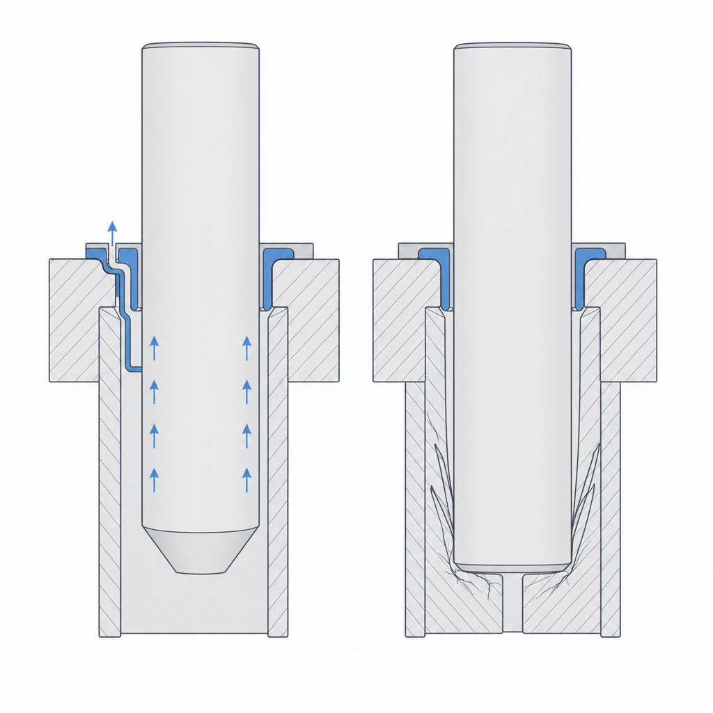
The first is blind or through. A blind hole traps air: when you push the shaft in, the air at the bottom compresses and pushes back, so part of the insertion force goes into overcoming that pneumatic spring. On a printed part the effect is smaller than it looks—FDM walls are porous and air leaks between the lines, so it rarely ejects the shaft—but it does stiffen the assembly and leaves the bottom at an uncomfortable pressure. If you need it blind, give it an escape route: a small vent connecting the bottom to the outside, or a relief or lengthwise groove in the shaft itself so the air slips out that way.
The second is round or splined. A round press-fit pin holds against axial pull-out, but not against turning: if friction is all that retains it, it spins in its hole the moment you apply a torque. To keep it from turning you need to break the symmetry: a rectangular section, a flat, or a splined profile. The splines also concentrate the interference on the crests, which bite and deform locally; the result is a more predictable grip than a smooth wall, which is forced to deform all over.
Inserting without galling or delaminating
Pressing the shaft in isn't just a matter of force. Push it in fast and the friction between the two surfaces generates heat. The plastic—which softens at very low temperatures—can melt locally and seize the assembly halfway, or relax on cooling and end up looser than you expected. Push the shaft in slowly, in one continuous motion; if it's a struggle, a drop of lubricant or soap cuts the friction and the heat without affecting the final retention. Bear in mind, too, that the plastic-on-plastic friction coefficient is high and variable, so the "friction from pressure" that retains the part is never as repeatable as a number in a table: treat it as a margin, not a guarantee.
There's one manufacturing variable that matters more than almost any other and decides how much interference is safe: which way the layers fall. In a hole printed with the shaft vertical, the hoop stress the interference creates pulls the layers apart—the weakest plane in the whole part—and the crack appears far sooner than if that same stress acted within a layer. If you can orient the part so the layers don't work in delamination around the hole, you gain margin for free. It's the first resort in Interference without cracking.
Creep: the joint that loosens over time
There's a failure you don't see on assembly day and that shows up weeks later: the part, which went in nice and tight, now wobbles. Nothing has worn. It's creep: under a sustained stress, the plastic slowly flows and relieves that stress, so the hole wall, stretched for months by the shaft, gives a little. The shaft, in compression, creeps too and adds its share. As both give, the effective interference drops, the contact pressure drops with it, and the grip relaxes.
Heat accelerates it enormously. Warm PLA flows with an ease it would never have cold, so a press-fit living near a motor, in the sun inside a car, or in a housing that heats up will lose grip far sooner than the same fit at room temperature. And unlike a clearance fit, here there's no margin to spare: the fit starts right at the limit of what you wanted, so any relaxation drops it below.
One last point worth keeping in mind: the same shaft, with positive clearance instead of interference, stops gripping and becomes an alignment pin. It holds nothing; it just locates two halves precisely before you bolt them together. It's the same part with the sign of the fit flipped, and it's worth recognizing, because sometimes it's exactly what you want.
Once you have the interference chosen, the next step is to make sure the wall takes it without splitting. To size the thickness, material, and orientation that head off the crack, go on to Interference without cracking; and if you're unsure what tenths to leave on your particular printer, Real printed clearances translates them into measured values.