Bell crank: turning force through 90 degrees
A bell crank is the most humble part in a linkage and the one that does the most work in silence: a bent lever that pivots on a single point and takes force in at one arm and delivers it at the other, turned through whatever angle you choose. Where a drive runs into a corner, the bell crank bends it; where a lever ratio is wrong, it rescales it. It has no gears, no springs, nothing that wears out except two pins. And that is exactly why it deceives you: it looks trivial until you print it weak at the elbow. It splits along a layer line on the third actuation, and you discover the whole control chain was drifting off because of the part you took for granted. What decides whether it holds isn't its shape — which is elementary — but three things: where the layers run through it, how much cross section you leave at the elbow, and how much clearance the pins have.
Two arms, a pivot, and a ratio
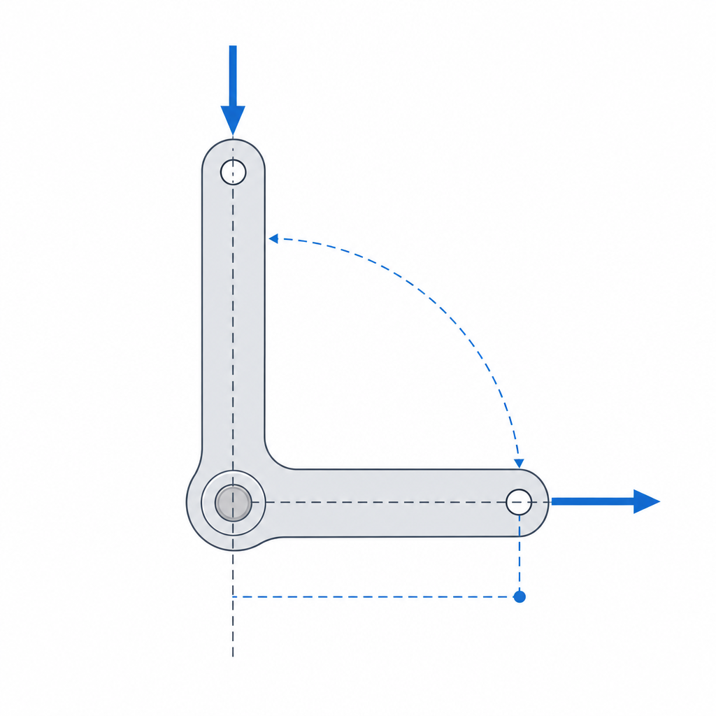
The kinematics are about as clean as it gets. You have two rigid arms joined at an angle, fused at a vertex, and the whole assembly rotates about a common pivot that lives at that same vertex. You push the end of one arm — the input — and, because the body is rigid, the other arm — the output — sweeps an arc around the pivot. The force coming in on one side goes out the other, redirected by the angle between the arms.
The split between force and travel is governed by the ratio of the lengths, always measured from the pivot to the point where each force is applied. The two arms are two levers sharing the same fulcrum, so the balance is a balance of moments: the input torque must equal the output torque, so the output force equals the input force times the input-arm length divided by the output-arm length. If the input arm is twice as long as the output arm, the force you deliver is doubled — but the travel is halved, because in the ideal frictionless case work is conserved, and what you gain in force you pay for in distance. Reverse the lengths and you get the opposite: less force, more travel. That's the whole of the arithmetic, and it's worth keeping in mind from the very first stroke, because the geometry you draw just to "make it fit" already fixes — whether you like it or not — how much force and how much displacement you get out.
Not just 90 degrees: redirect and rescale together
The name suggests the bell crank is the device that turns force through a right angle, and that is its typical case, but the angle between the arms is a free parameter. Set them at 90 degrees and the output ends up perpendicular to the input; open them to 120 degrees or close them to 60 and the output points wherever the elbow aims it. This lets you solve packaging geometries that a straight tie rod can't: bring a drive in through a gap and send it back turned just enough to dodge another part.
On top of that redirection — and independent of it — you can also rescale the arm lengths. They are two degrees of freedom you can tune separately: the angle decides where the output goes; the arm ratio decides how much force and travel it carries. One and the same bell crank can simultaneously bend a control 90 degrees and double its force, or redirect it 45 degrees while reducing it. That's why it shows up so often as an adjustment point within a longer rod chain: it's the place where, without adding parts, you slip in the change of direction and the lever-ratio correction the rest of the chain needs.
What it's actually for
The bell crank lives where a drive has to turn a corner. The typical case is the linkage of brakes or controls, where a cable or rod arrives in one direction and the actuator it has to move sits 90 degrees away: the bell crank picks up the pull and delivers it redirected, with no pulleys and no forced bends in the cable. The same goes for control runs — rudders, gates, remote levers — and for the internal transmission of a mechanism where the motor or spring pushes along one axis and the load lives on another.
The second use, less obvious, is as a lever-ratio adjustment point within a chain. When you chain several rods to carry a motion from one end of the part to the other, the bell crank is where you correct the ratio: the natural place to insert whatever amplification or reduction is missing, since you're changing direction there anyway. Designing the chain with the bell crank in mind as that adjustable joint usually comes out cleaner than trying to balance forces and travels segment by segment.
Elbow and pins: the critical zones
This is where FDM exacts its toll, and where a part that's trivial on paper turns delicate. The load is not shared evenly: the pivot and the junction of the two arms concentrate the entire moment. Each arm is a lever, and the moment each one generates — force times the arm perpendicular to that force — is carried entirely by the elbow and the pivot. That is the section you have to size for the maximum moment of the travel, not for the nominal force at rest. A slender elbow that holds the gentle push of assembly snaps when the mechanism works against a stop.
The print orientation decides the failure mode before any dimension does. The load in the arms is bending: the arm works by flexing around the pivot, and that bending puts one face of the arm in tension. If you print the part so the layers end up perpendicular to that tension, the force pulls directly on the bond between beads — the weak plane of the part — and the arm delaminates, splitting along a layer line instead of tearing through sound material. What you want is to lay the bell crank flat on the bed, with the plane of the arms parallel to the layers, so the bending runs along the beads instead of peeling one layer off the next. The same orientation also solves the pin eyes at once: laid flat, the perimeters of each eye wrap the hole layer by layer, which is exactly how you want each eye wall to work. It's the principle that governs any part that flexes or transmits load, developed in Layer orientation for motion: orient so the load runs along the bead, not between layers.
And then there are the pins. A bell crank has at least three articulated points — the pivot and the eyes where the input and output rods hook in — and all three are pin eyes loaded in shear and bearing. Give them enough material: an eye is a hole surrounded by little wall, and that wall works in circumferential tension every time the pin pushes on it. Too thin and the eye opens up or splinters; thick enough, with several continuous perimeters around the hole, and it holds. Treat each eye as a zone to reinforce on purpose, not as a hole left wherever it happens to land.
| Zone | What loads it | How to size it |
|---|---|---|
| Elbow (arm junction) | Maximum moment of both arms | Solid, generous section; fillet at the vertex |
| Pivot | Total reaction + stress concentration | Reinforced eye or hub, thick wall, correct rotational clearance |
| Rod eyes | Shear and bearing of the pin | Several continuous perimeters around the hole |
| Print plane | Bending of the arms and wall of the eyes | Part laid flat in the plane of the layers, not on edge |
The pivot clearance: neither binding nor wobbling
The pivot has two demands that pull in opposite directions, and you have to serve both at once. It has to turn smoothly — if it binds, the drive turns stiff and erratic — and it has to turn without play — because any extra clearance in a pin translates into backlash, into dead motion that travels through the entire control chain. In a linkage with two or three joints, the play of each pin adds up: a few tenths at each joint become a millimeter or so of slack at the pivots, and the lever ratio of each bell crank can amplify that millimeter into several of dead travel at the control — the stretch you move before the mechanism responds at all.
That's why you don't guess the pivot clearance: it's your printer's sliding fit, measured and known — no more, no less. Too tight and friction makes the bell crank bind; too loose and you introduce backlash. The exact number comes from calibrating your machine, not from copying a table, and it's the same reasoning that applies to any moving part: it's spelled out in Tolerances for moving parts. Remember too that the printed hole tends to come out narrower than its nominal dimension, so the clearance is budgeted against the measured hole, not the drawn one, and it's better to get there by opening up the eye rather than thinning the pin, which is the part you don't want to weaken.
Fatigue and material: surviving the thousandth actuation
A control bell crank isn't actuated just once: it's actuated thousands of times. And FDM doesn't fail only by static fracture against a stop — it fails by fatigue, by a delamination that advances a little with each cycle until the elbow or an eye opens along the very layer line you'd taken for sound. Sizing for the maximum moment is necessary but not sufficient: leave margin above that maximum, because the part doesn't see the load once but repeated. And if the mechanism carries a spring that holds tension at rest, creep comes into play: loaded plastic flows slowly, and PLA is the worst offender here, so a pretensioned arm can give and lose its position over months. For a bell crank that works hard or that lives under sustained load, step up from PLA to a tough material — PETG or nylon — and orient the layers properly; you gain fatigue resistance exactly where the part is weakest.
With the elbow sized for the moment, the layers oriented so the bending doesn't delaminate, and the pin clearance set to your machine's sliding fit, the bell crank stops being the part you took for granted and becomes the reliable joint of the chain. And since almost everything in a printed mechanism ends up coming down to which tenth of a millimeter sits between the pin and the eye, the next step is that number: Tolerances for moving parts takes you from what the part does to the gap you actually have to draw.