Interference without cracking
You push a shaft into a hole that's a hair too narrow, press, and the part grips by friction: that's an interference fit, and it's the cleanest way to fix a knob, a bushing, or an insert in place without screws or glue. In metal it's barely a problem. In FDM it's a serious one: the same grip that acts as a brake also puts the wall of the hole in tension, and the wall of a printed part fails at its weakest point. Press a little too hard and the boss doesn't yield elastically the way you'd expect — it splits top to bottom along a layer line, almost always on the first assembly. This article is about why it happens exactly there, and how to size things so it doesn't.
How the grip opens the hole
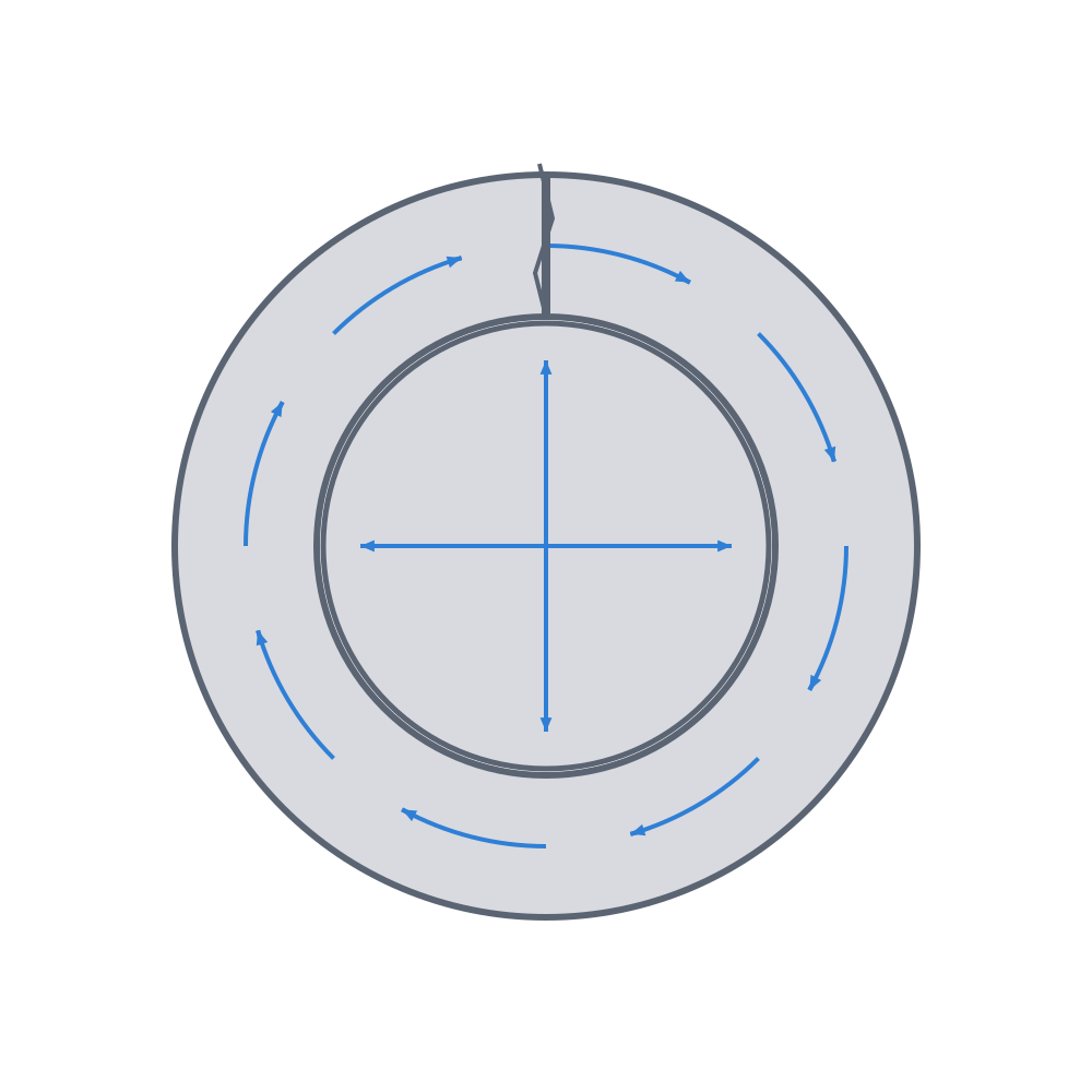
When you force a shaft into a smaller hole, the material doesn't vanish: it gets pushed outward. The wall around the hole has to stretch to make room, and that stretch is a tension running in a circle around the hole. It's called hoop stress, and it's the same physics that swells and bursts a balloon or a pressurized tube: the force points radially outward, but the wall resists by working in a circle, pulled in tension tangentially.
This has a consequence worth being clear about before touching a single number. Hoop stress doesn't crush the wall — it opens it. It pulls each part of the wall away from the next, as if to straighten the ring into a strip. A solid, homogeneous wall would carry that distributed tension without yielding. The trouble is that the wall of an FDM part is neither solid nor homogeneous.
Why it splits at the seam, not through solid plastic
A printed part is a stack of beads welded to one another while still hot. That weld never reaches the strength of solid plastic: between layers the bond reaches only 50–90% of the strength the material has along the bead, and it drops toward the low end when cooling is excessive or extrusion temperature is low (Layer adhesion and anisotropy covers this). The perimeter also has a singular point, the seam, where each loop of the perimeter starts and ends. There the bead starts cold and overlaps onto itself, leaving a weaker bond and often a small visible valley.
Don't confuse the two weaknesses — they sit in different planes. The between-layers weakness is a horizontal plane, perpendicular to the Z axis. The seam is a vertical line, running layer by layer through the same point on the perimeter. In a boss printed standing up, hoop stress is tangential and horizontal: it doesn't separate the horizontal layers — that orientation is the right one for hoop loading — instead it pulls the vertical seam open. That's why the boss doesn't break through the good plastic: it unzips along the seam, top to bottom, like a zipper. The interference crack is so clean and so vertical because it follows a defect that was already there, not breaking sound material.
Thicken the wall — and make it all perimeter
The first defense is geometry: give hoop stress more cross-section to spread across. The reliable rule of thumb in PLA and PETG, for small bosses (Ø2–8 mm), is that the outer diameter of the boss should be at least twice the hole diameter: a minimum wall thickness equal to the hole radius on each side. Below that, the wall is so thin compared with the force opening it that any reasonable interference takes it to the limit. For large holes the multiple stops making sense: a 10 mm wall around a Ø20 hole is absurd. There, size by absolute wall thickness and contact pressure, not by a fixed multiple.
But thickness alone isn't enough if that thickness is infill. Sparse infill does little against hoop tension: it's a mesh of crossed strands with gaps, not a continuous ring. What truly resists hoop stress is the perimeter, the bead that goes all the way around the hole without a break. So design the boss so the wall is practically all perimeter: with a 0.4 mm nozzle and a ~0.45 mm bead, three or four perimeters give ~1.35–1.8 mm of continuous wall working in a circle. Add perimeters in that zone before you raise the infill; here the infill barely counts.
Chamfer the mouth of the hole — a 0.5–1 mm lead-in at 30–45°. It's not for looks: as insertion starts, all the grip concentrates on the upper edge of the hole, and that edge is also where the first layers end. Without one, the shaft splinters the mouth on the way in and hands the crack a starting point. The chamfer guides the shaft in straight and spreads the force peak over a ramp. Bear in mind that a chamfer printed standing up comes out stepped, layer by layer; modeling it as a smooth cone, or a light deburr, leaves it guiding cleanly.
| Parameter | Starting value | Why |
|---|---|---|
| Boss OD | ≥ 2 × hole Ø (Ø2–8 mm) | spreads hoop stress over more cross-section |
| Perimeters in the wall | 3–4 (near-solid wall) | only the perimeter resists the hoop; infill doesn't |
| Lead-in chamfer | 0.5–1 mm at 30–45° | avoids splintering the mouth on insertion |
| Interference, plain cylinder | 0.05–0.15 mm on Ø | tenths, not microns (see below) |
| Interference, with ribs | 0.2–0.3 mm on Ø | the ribs yield, not the wall |
Spread the interference: line contact, not the whole ring
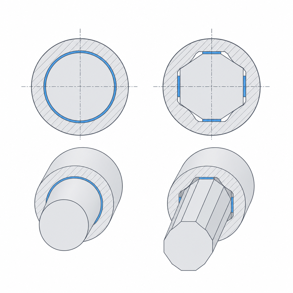
The strongest defense isn't to resist hoop stress better — it's to avoid generating it. A plain cylinder pressed in pushes the whole wall outward at once, because the contact is a continuous ring and the displaced material has nowhere to go but against the wall. Swap that continuous contact for line contact and the problem nearly disappears.
There are two ways to get there. The first is ribs or knurling: a few thin longitudinal ribs in the hole (or on the shaft), so the interference lives only on those ribs. On the way in, the ribs crush and yield (that's what they're for), so the grip concentrates on them and the wall sees almost none of it. To keep them printable and not brittle, make them at least one bead wide (~0.45 mm) and put little interference on each rib. The ribs also absorb your printer's variation: three or four are enough, and because they yield instead of the wall, the fit comes out repeatable.
The second is to use a non-circular profile — hex or square — instead of a cylinder. A hex shaft bears on its six edges, not on a ring. The interference spreads into discrete zones, and between one edge and the next there's a gap where the displaced material can flow instead of pushing against the whole perimeter. That sharply reduces the hoop-stress peak and, as a bonus, the profile locks rotation: it transmits torque without the shaft slipping, which is what you want for a knob, a crank, or a gear on its shaft.
Orient the seam, warm it to insert, and budget in tenths
With the geometry sorted, three levers remain, and all three cost little.
Orientation. Since the crack follows the seam, place it where hoop stress won't open it. If the boss prints standing up, its vertical seam lines up with the plane of maximum tension, the worst possible case. Moving the seam to an unloaded zone turns a boss that splits into one that holds — without changing a single dimension. Laying the part down is riskier: it changes the failure mode — now hoop stress crosses the horizontal layer planes, which are the weak between-layers ones — and, in a hole, overhangs and supports degrade the roundness and the tolerance of the fit. A hole printed vertically comes out more cylindrical than one laid down. It's the flip side of what Tolerances for moving parts explains: orientation decides which way the weakness points.
Temperature. Insertion force isn't linear with interference, and plastic softens before it melts. With metal inserts this is standard practice, not a shortcut: the hot insert melts the wall locally and seats with little force (heat-set). With plastic against plastic, the effect is more marginal and risky. PLA's Tg is around 55–60 °C; warm water (35–45 °C) barely softens it, and to feel any real effect you'd have to approach that Tg, where PLA starts to relax and deform permanently: instead of "recovering and gripping just as hard," it can lose interference. And on cooling, differential thermal contraction shifts the final dimension of the fit. Save the heat for metal inserts; with plastic bosses, trust the geometry instead.
Interference budget. Here's the mistake that splits the most bosses. Printed interference is budgeted in tenths of a millimeter on the diameter, not in the microns of a machining fit — FDM's variation would swallow those microns and leave you a loose clearance instead of a grip (Press-fits that hold covers this). Start from the measured hole: on the order of 0.05–0.15 mm of diameter excess on a plain cylinder, and 0.2–0.3 mm only if the ribs yield for you.
But don't overdo it the other way. Too much interference fails in two ways. One is immediate: it cracks on assembly, along the seam, as we've seen. The other is treacherous: the part goes in perfectly and days later loosens on its own, because the loaded plastic flows slowly and releases the tension that was gripping it — the creep that Press-fits that hold details. PLA is the worst at this, and service heat speeds it up. That's why a conservative interference with the right geometry always beats an exaggerated one: the first grips forever, the second is a crack with a delivery date.
The exact number of tenths comes from measuring, not guessing. Print several bosses with stepped interferences, insert them, and see which one holds without cracking: the method of Real printed clearances applied to grip instead of clearance. That coupon is worth more than any table.