Magnetic detent: states defined by magnets
A classic detent marks its positions with a ball and a spring: something rubs, something snaps, something wears. A magnetic detent does the same thing with nothing touching. Two magnets embedded in plastic seek each other out, fall into their minimum-energy position, and hold it with a force that needs no contact; there is no noise and no friction wear over the cycles. The hard part is that this force does not distribute the way you'd like: it collapses with distance, so the entire behavior of the mechanism—how firm the closure is, how well-defined the state is—is decided in the fraction of a millimeter of air and plastic you leave between the two magnets. That gap is the dimension you design; everything else is geometry that supports it.
Force falls off with the air gap, and that's the virtue
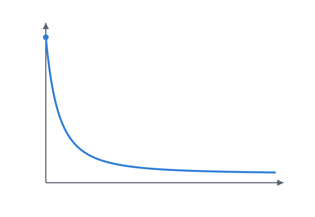
The reason a magnet works as a detent and not as some vague all-purpose glue lies in how its force decays. The attraction between two facing magnets does not drop off smoothly and linearly with separation: it falls fast, and that is exactly what turns it into a useful energy well rather than a vague pull you feel everywhere. Far from alignment the force is so weak it barely counts; as soon as the faces close the last tenths of a millimeter, it climbs hard and the part seats firmly. Without that nonlinearity you'd have a magnet that pulls a little throughout the travel and defines no position at all: a paperweight, not a detent.
It's worth not settling on a single number for that falloff. The exact exponent depends on the magnet's geometry: in the regime that actually matters for a detent—two facing faces with an air gap very small relative to the magnet's size—the force is high and relatively flat, and only truly collapses once the separation approaches the magnet's own dimensions. The practical rule is the one that survives every nuance: distance matters far more than the strength of the magnet. A modest neodymium magnet at 0.3 mm from its mate holds more, and with a more defined state, than a powerful one at 2 mm. That's why the dimension governing the feel of the mechanism is not the quality of the magnet you buy, but the thickness of plastic you leave between it and the contact surface. Work that distance before anything else.
Polarity is one more dimension, and the one most often forgotten
A magnet has two faces and only one is useful. Opposite faces attract—that's your closure, your automatic centering; like faces repel, and repulsion isn't a defect to avoid but a tool: with it you build bistability (two stable positions separated by a repulsion point that forces a commitment to one) or a return that pushes the part back to its rest. But that decision has to be made part by part and pocket by pocket, because the magnet gives no warning of its orientation once it's embedded in opaque plastic.
Here's the most trivial and most frequent failure mode: mounting a magnet backward. The part comes out perfect, the pocket fits, and when you bring the two halves together, instead of closing, they repel. There's no way to fix it without removing the magnet, which you've already glued or captured. The defense is to plan the polarity of each pocket before printing and to mark it physically—a dot, a notch, an asymmetric recess in the part—so you don't rely on memory at assembly time. And when gluing, check the attraction against the mating part before you release the adhesive, not after.
What it's for: silent closure, wear-free control
The magnetic detent shines exactly where the mechanical detent gets in the way. A self-aligning closure—a lid that finds itself and stays firm—benefits from the force appearing only at the end of travel: the lid approaches with no resistance and seats with a dull, mute thud, no tabs rubbing, no audible click. In a knob or selector with few positions, the magnets define the stable points without a ramp that gets filed down with use: the feel today is the feel ten thousand operations from now, because nothing touches. And in any application where you don't want mechanical contact—something that must open clean, with no wear particles, or run silently—the magnetic detent gives position without paying friction.
The usage limit is the flip side of that virtue: because the force falls fast with the air gap, don't expect a magnetic detent to define many positions close together or to hold across a large separation. It's for few states, well spaced, and short-distance closures. For many positions in a row, a mechanical detent with its ramp still wins.
FDM design: capturing the magnet and metering the air gap
Embedding a magnet in a printed part is three decisions, and all three matter. The first is how you hold it, and here it's worth remembering that sintered neodymium magnets are ceramic and brittle: a real press fit on the magnet chips or cracks it easily, especially on thin discs, and a chip on the edge lands right on the closing face. So the default fixing isn't direct interference on the magnet, but a pocket sized to it with a light nominal clearance and a dot of adhesive, or—better still—a bridged layer: you pause the print, place the magnet, and the slicer lays a plastic ceiling over it, leaving it captured without glue. The pocket clearance is reasoned like any other fit—in tenths, against the real dimension of the printed hole, not the nominal one; you'll find it in Tolerances for moving parts.
The second is the plastic wall between the magnet and the contact face. Never let the magnet sit flush: a wall protects the magnet, prevents the magnet-on-magnet impact between the two halves—which chips the neodymium edges—and gives you a clean closing surface. But remember the physics above: that wall is air gap, and the air gap punishes force without mercy. Every tenth of plastic you add as protection costs you attraction disproportionately, and there are two facing walls, one per half, that add up: count both when estimating the real separation between magnets. The compromise is to leave that wall as thin as it'll print well, and not one layer more.
Here the bridged layer imposes its own condition: a ceiling printed over the magnet's void tends to sag, and it sags more the larger the diameter it has to span. A Ø4 bridges clean with little; a Ø10 droops at the center right on the face you wanted flat. So don't fix the wall at an absolute number: count it as a function of the magnet's diameter, giving as many layers as it takes for the bridge to close flat over that void. Two layers usually suffice over a small magnet and fall short over a large one.
The third is to signal the polarity in the model itself, as we already saw: a recess or a mark that makes it impossible—or at least awkward—to mount the magnet backward.
| Parameter | Starting value | Why |
|---|---|---|
| Magnet capture | nominal clearance + adhesive, or bridged layer | direct pressure chips the neodymium; adhesive or the bridge fix it without cracking |
| Wall to the closing face | minimum viable for the magnet diameter | protects and closes flat; every tenth kills force, and a large void sags the bridge |
| Pocket clearance | light, set with adhesive, no lateral play | a loose pocket lets the magnet escape and shifts the stable point |
| Polarity mark | notch or asymmetric recess | prevents mounting the face reversed |
| Thermal grade | matched to the service environment | SH/UH/EH raise Tmax at the cost of force |
The failure modes: orientation, clearance, neighboring magnets, and heat
Four things ruin a magnetic detent, and it's worth keeping all of them in mind before printing. The first you've already seen: the misoriented magnet, which repels when it should attract; you prevent it by marking and verifying, not by correcting. The second is the too-loose pocket: if the magnet rattles in its hole, it works its way out with use or, worse, shifts a few tenths and drags the point of maximum attraction with it, so the state lands where you didn't expect. A magnet pocket wants a fit with no lateral play, and the way to get there without cracking the magnet is light clearance plus adhesive, not squeezing.
The third shows up when you put several magnets close together: each one has its own field, and a neighboring magnet pulls or pushes on the one you're using, shifting the energy well from where you calculated it. The sign of the effect depends on the relative polarities: opposed neighbors help define states, neighbors in the same sense leak sideways and soften the well. Since the interaction falls off fast with separation, the practical rule is simple: space the pockets at least several times the magnet diameter apart, or account for their interaction from the start instead of discovering it once assembled. And watch nearby ferromagnetic parts too—screws, inserts—that bias the well just like a neighboring magnet.
The fourth isn't geometric but thermal, and it gets forgotten: neodymium loses force with heat and, past a certain point, demagnetizes permanently. A standard N35–N42 has a maximum temperature around 80 °C, and there the real risk of the bridged layer isn't the nozzle, which passes fleetingly, but that the magnet sits on the freshly printed floor above the hot bed for the rest of the print. With PLA and a bed at 60 °C you have margin to spare; with PETG and a bed at 90 °C, a magnet near the bed can brush or exceed its loss threshold. A part that lives in the sun, next to a motor, or stuck against a hot bed will see its detent soften over the months. Choose the magnet's thermal grade by where it will work—the SH, UH, or EH grades raise the allowable temperature at the cost of force—not just by its attraction at room temperature.
The magnet gives the force; the geometry gives the direction
The last idea is the one that separates a detent that works from a magnet that merely sticks. Magnetic attraction is omnidirectional: it pulls the part toward alignment along every path at once, sideways included, and on its own it doesn't guarantee that the two halves reach the right point. More than that: two flat facing faces don't self-center—they slide toward maximum overlap, which may not be the center you wanted. If you need some self-centering from the magnet itself, a conical or countersunk geometry, or a magnet seated in a cup, provides it; but the robust solution doesn't rest on that.
That's why a firm magnetic detent is almost never just magnets: it carries a mechanical stop or guide that fixes the approach axis—a pivot, a lip, a pair of pins—so the part can only move along the direction the magnet wants to take it. And it's worth being precise about what each part contributes: the sharpness and repeatability of a state come from that geometry channeling the motion, not from the field's decay; the magnet contributes the force that seats the part and holds it once it's on track. Divide the work this way: the geometry constrains the degrees of freedom and sets where the part comes in; the magnet supplies the force. That division is the recipe for a firm, repeatable, silent detent. And since it all revolves around embedding the magnet well and sizing its pocket, the next thing worth reading is how the components you put inside the plastic are housed in general: Embedded hardware: magnets, bearings, and inserts.