Self-locking worm: won't backdrive from the output
A worm screw meshing with a worm wheel does something no train of spur gears does on its own: turning the input moves the output, but turning the output doesn't move the input. The wheel pushes against the worm's thread with all its force and the assembly doesn't give; it stays pinned where you left it, holding the load with no motor, no brake, and without burning a single joule. That's self-locking, and it's neither magic nor an assembly trick: it's a comparison between two angles that either passes or fails. Understand it and you have a no-back and a high-ratio reducer in a single stage. Take it for granted and you have a part that holds on the bench and slides on its own the day it matters.
What decides the lock: two angles
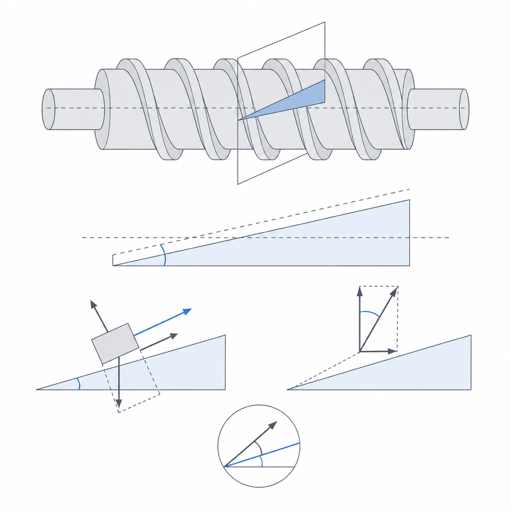
The worm's thread is a ramp wrapped into a helix. When the wheel tries to drive it, its teeth push against the flank of that ramp, and that force resolves just as the weight of an object on an inclined plane does: one part tends to roll the worm forward — the useful component, the one that would transmit motion backward — and another presses the thread flanks together, generating friction. Which one wins settles it.
The component that pushes the worm to turn grows with the steepness of the ramp — the worm's lead angle λ, the slope of the helix measured against the plane perpendicular to the axis. A very shallow helix, almost a fine-pitch screw, offers a gently inclined ramp; an aggressive helix, with a large pitch or several starts, presents a steep ramp that the wheel climbs easily. Opposing that component is friction, quantified by the friction angle φ: the arctangent of the friction coefficient of the contacting material pair. In its simplest form the condition is straightforward:
| Quantity | What it is | Effect |
|---|---|---|
| Lead angle λ | Slope of the thread's helix | Higher → easier to backdrive |
| Friction angle φ = arctan(μ) | Friction of the material pair | Higher → more resistance to backdrive |
| Self-locking | Holds approximately when λ < φ | The wheel can't move the worm |
As long as the lead angle stays below the friction angle, the force the wheel exerts on the thread isn't enough to overcome friction, and the assembly stays fixed by itself, with no external brake. There's a nuance the simple formula hides: the worm's flank isn't flat but has a pressure angle αₙ, and that inclined flank distributes the force so that the true limit is a little more generous — tan λ < μ / cos αₙ. The pressure flank works in your favor, making self-locking slightly easier to achieve than the square-thread version suggests. But the direction of the reasoning doesn't change: a small lead angle locks; a large one doesn't.
Drop the idea of a sharp boundary. Around λ ≈ φ there's no line separating "locks" from "doesn't lock," but a gray band in which the assembly sometimes locks and sometimes doesn't, depending on the condition of the contact at that moment. The practical rule in industry isn't to graze the limit but to stay clearly below it: a worm that barely satisfies λ < φ is no longer reliable, even in metal. Designing near that band is designing on the edge of failure.
Reducer and no-back in the same stage
What makes the worm special is that those two angles aren't chosen separately. The same shallow helix that produces self-locking gives you a huge reduction for free. The transmission ratio is i = Z_wheel / Z_starts: the number of teeth on the wheel divided by the number of starts on the worm. A single-start worm against a forty-tooth wheel gives 40
in a single stage — something that would demand several trains in series with spur gears; the same worm with two starts would give 20, so the number of starts is not a minor choice.The kinematics explain why: the thread is like a screw, and the wheel a nut forced to turn rather than translate. Each turn of the worm advances it by as many teeth as the thread has starts. A small advance per turn means two inseparable things: a lot of reduction and little slope. And little slope is exactly what self-locking asks for. That's why a high-ratio worm tends to be self-locking naturally, and why a fast one — several starts, little reduction — almost never is.
That combination is the reason to use it. It serves positioners that must hold a load without burning energy to hold it: a valve that stays at its opening, a print head that keeps its angle, an adjustment that won't drift. And it serves as a no-back when you also want a lot of reduction, taking the place of a ratchet or a wrap spring in cases where you already have a screw stage in the train. A single part gives you the reduction and the directional lock; you don't need a separate mechanism to keep the output from backdriving.
All of this has a price, and it's worth knowing what it costs. The contact between thread and tooth is sliding, not rolling as in a spur gear: the worm's surface sweeps across the tooth's flank at each pass. That sliding is precisely what dissipates the return energy and gives you the lock, but it's also what makes the worm inefficient in the forward direction and what turns that friction into heat. And here there's a hard physical constraint: any worm capable of self-locking has a forward efficiency below 50%. In plastic, with the high friction of the dry pair, that efficiency easily drops to 20–40%: for every joule you put in, more than half is lost to friction before it reaches the wheel. Low efficiency and heat at the contact aren't defects to fix; they're the visible face of the same phenomenon that holds your load.
Printing it in FDM: helix, sliding, and delamination
The orientation rule dominates over almost everything else. Print the worm with the axis vertical, so the helical thread grows layer over layer, winding around the axis. That way the helix comes out continuous and clean, each turn resting on the one below. Laid down, the same thread becomes a succession of overhangs that droop on one side and hang in the air on the other: the underside of each turn comes out unsupported, stepped, and stringy, and the geometry of the flank — the ramp the lead angle depends on — stops being reliable right where it has to be finest. Orientation isn't cosmetic here; it changes the dimension that decides whether the part locks, for the same reason Layer orientation for motion lays out.
But the vertical axis has a downside you have to confront. With the axis vertical, the layers sit perpendicular to the axis, and the return torque loads the thread in FDM's weakest direction: in shear between layers, exactly where a part delaminates. A self-locking worm exists to withstand the torque the wheel returns to it, and that torque pulls on each turn of the thread, trying to peel it off the one below. If you print with few perimeters or a low temperature, the part will lock on the bench and delaminate the first time it takes a real load. Raise the perimeter count, raise the extrusion temperature so the layers weld well, and treat the thread as a feature loaded in shear, not as a helical ornament.
The sliding contact, which in metal already calls for lubrication, is the Achilles' heel in plastic. Each pass of the tooth sweeps the flank of the thread, dragging material against material, and dry PLA and PETG have high friction and poor wear resistance under friction. That pushes you toward two decisions. The first: choose a low-friction, wear-tolerant material for at least one of the two parts — a worm in a self-lubricating plastic against a tougher wheel, for example — and take care of the flank finish so the sliding doesn't bite into steps. The second: verify which side of the gray band the worm that actually comes off the printer falls on, not the nominal one you put on the screen. Bear in mind that the danger here isn't the one the metal manuals dramatize.
A reality check is in order here. Dry PLA and PETG have μ ≈ 0.3–0.4, which gives a friction angle φ of about 17–22°. To lose self-locking, the lead angle would have to exceed those 17°, and that corresponds to multi-start, high-speed worms — precisely the ones almost nobody prints to hold a load. A single-start worm with a 40
ratio has a lead angle of barely 2–5°: nowhere near the limit. So for a normal self-locking geometry in FDM, the margin against the gray band is enormous and is rarely your problem. The danger of "landing on the wrong side of the band" only applies to deliberately fast designs. The failure mode that will actually bite you is another one: the wear and creep of the plastic.The clearance between thread and tooth is the other number that decides the result, and you reason about it like any moving fit. Too tight and the worm binds as it turns, adding parasitic friction to the already high friction it has by nature; too loose and you get backlash, that dead play in which the input moves a little before the output responds. It comes from calibrating your printer, not from guessing, exactly as Tolerances for moving parts explains.
The failure modes: how the lock is lost
A self-locking worm fails in specific ways, and almost all share a symptom: the wheel begins to be able to move the input when it couldn't before. They're worth naming because none of them warns you until the load slides.
The first is the outright loss of self-locking from a drop in friction. The λ < φ condition rests on a friction angle you assumed; if the real friction is lower, the comparison flips. It happens two ways. If someone lubricates the contact thinking it helps — in a metal power-transmission worm it often does — the friction coefficient collapses, φ drops, and the lock vanishes: here grease hurts rather than helps. It also happens with wear: as the plastic flank polishes and smooths with use, its friction drops, and an assembly that locked on day one can stop doing so after a few hundred cycles.
The second is the cold creep of the thread under static load, and it's the most treacherous because it needs neither rotation nor sliding nor vibration. The worm's signature use case is holding a stationary load for hours or days, and PLA or PETG, under constant contact pressure, flow slowly: the thread's tooth deforms little by little, the contact gives a few tenths, and the output sags even though nothing turns. It isn't wear, it's viscoelastic deformation of the plastic itself. A positioner that looks solid in the first minute can have lost its setting the next day from creep alone. The finer the thread and the warmer the environment, the faster it flows.
The third is the rapid wear of the thread under continuous load. Plastic isn't the bronze of an industrial worm: under sustained contact pressure and with sliding, the flank wears, and with it you lose both load-bearing section and geometry at once. The wheel starts biting into a thinner, worse-formed thread, which reduces the torque it can hold and shifts the effective lead angle.
The fourth is the backlash that reappears with wear. Even if you calibrate a tight clearance when printing, the material that wear removes from the flank becomes play: the worm turns a little more before the wheel responds. In a positioner that's position error accumulating over hours of use, and in a no-back it's the wheel gaining free travel before it meets the resistance that should have been immediate.
Self-locking is not a safety brake
There's one last nuance that separates the engineer from the hobbyist, and it's a matter of judgment, not calculation. Self-locking resists a static torque applied slowly: the wheel pushes, the ramp pushes back, friction wins, and the assembly stays still. But neither the ramp nor the friction is meant to absorb an impact or a sustained vibration. An impact introduces energy instantaneously, beyond what static friction can manage, and vibration does something more insidious: it makes the contact microslip thousands of times, and in each microslip the friction holding the load is the dynamic coefficient, lower than the static one. The wheel "walks" tooth by tooth, imperceptibly, until the positioner has lost its setting or the load has dropped on its own.
That's why self-locking is a convenience, not a guarantee. To hold something whose failure truly matters — a load that could fall on someone, a mechanism that must stay closed under any condition — self-locking holds under normal conditions, but the safety is provided by a dedicated element that doesn't depend on a balance of angles: a pawl that locks mechanically, a brake that bites independently of contact friction. The worm stays still 99% of the time; the pawl is there for the 1% when a vibration makes it stop.
Deciding how much margin to give that comparison is, at bottom, the same problem as any printed fit: the number you draw isn't the number that comes off the bed. Before you trust that your worm locks, measure the real clearance and flank geometry with the method in Tolerances for moving parts, and check on the part — not on the model — which side of the band it landed on.