Lead screw stage: turning rotation into linear motion, with force
A lead screw is the most honest way to move something in a straight line, with force: a screw that, as it turns, drags a nut along its axis. As it turns, it multiplies your torque into a thrust you wouldn't expect from a small motor. There's no magic here — just an inclined plane wrapped into a helix. But that same helix that hands you force also decides whether the stage advances fast or slow, whether it backdrives on its own under load or stays put where you left it, and whether the printed thread survives ten cycles or strips on the first one. Almost everything comes down to two numbers — the pitch and the helix angle — and to one decision people tend to put off: whether you print the load-bearing thread or buy it.
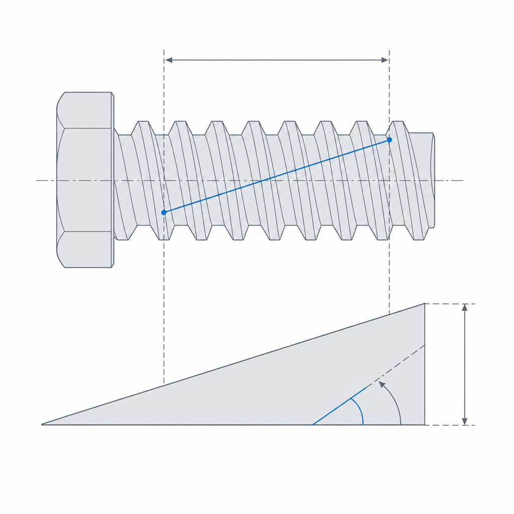
The helix turns rotation into travel, and torque into force
A thread is an inclined plane wrapped around a cylinder. Each full turn of the screw moves the nut by exactly what we call the lead: the pitch times the number of starts. A single-start thread with a 2 mm pitch advances 2 mm per turn; a two-start thread with the same pitch advances 4 mm. That number is the gear ratio of the whole stage, and every other decision follows from it.
The mechanical advantage comes from the geometry of that inclined plane. The helix angle measures how much the ramp climbs per turn: it's the angle whose tangent equals the lead divided by the circumference of the thread's mean diameter. A small lead gives a small helix angle — a shallow ramp — so you travel a long angular distance to gain one linear millimeter, and that long detour is what multiplies the force. A small pitch gives you high thrust and little travel — what you want in a press or a clamp, where there's travel to spare and force in short supply. A large pitch does the opposite: large helix angle, steep ramp, advances quickly with little torque, useful when you want speed and the load is light. You can't have both; you're choosing how to spend the motor's turns: on force or on distance.
Self-locking: holding position without a brake
There's a property of the helix that's invaluable in a linear stage: self-locking. If the helix angle is smaller than the friction angle of the screw-nut pair, the nut cannot make the screw turn no matter how hard it pushes axially. Put another way: you turn the screw and the nut advances, but axial load on the nut can't turn the screw in reverse. The stage doesn't backdrive under load; it holds position without continuous energy or a brake.
The physics is the inclined plane again. Pushing the nut against the helix is the same as pushing a weight up a ramp: if the slope is gentle and friction is high, the weight doesn't slide — it grips. That's why a small pitch tends toward self-locking — its helix angle is small, so the slope falls below the friction cone — and a large pitch, with its steep ramp, tends to backdrive. If your clamp has to keep its grip with the motor off, or your lift can't drop when you let go of the crank, you want to be on the self-locking side.
This is where the thread profile matters more than anywhere else. Acme and trapezoidal threads — flanks at 29° or 30°, a thick, flat-crested tooth — are used in power screws precisely for two reasons that reinforce each other: their robust section resists the axial load without stripping, and their wide-pitch, low-helix-angle geometry sits naturally in the self-locking range. The fine triangular thread of a metric bolt is meant for clamping, not for transmitting motion under repeated load.
Print the thread or buy it: where printing stops working
Here FDM reality is unforgiving, and its limits are hard. It's worth separating two uses people mix up: for a printed fastening screw, which only clamps and doesn't carry repeated load, M8 or larger comes out reasonably well; a motion screw under load is a different story, because fine metric threads simply aren't power screws — their shallow tooth and 30° flanks round over and stop gripping. The practical floor there is a trapezoidal profile like Tr8, and better still Tr10 or Tr12. Fine threads simply don't print cleanly: the tooth is smaller than what your nozzle can resolve with two beads, so the crests end up rounded and the valleys filled. The profile that carries the load blurs until it no longer grips.
Orientation decides the outcome. Print the screw vertically, with the axis perpendicular to the bed: that way each turn of the helix is spread layer by layer, continuously, and the profile comes out clean and symmetric. Printed lying down, the thread crosses overhangs on its underside; it comes out collapsed and asymmetric, with one flank not matching the other — fatal for a pair that has to slide smoothly. This is the same logic as Layer orientation for motion applied to a helix: the direction of the layers decides which way the weakness points, and how faithfully the load-bearing geometry comes out.
Printed vertically, the flank profile is set by layer height, not bead width: the tooth needs several layers to have a real profile — a 1.5 mm pitch with a 0.2 mm layer gives about seven layers per pitch, and only coarse pitches clear that bar. And there's a detail specific to vertical printing that's costly to forget: the Z seam. The line where the slicer closes each turn leaves a scar that the thread flank crosses pitch after pitch, and that translates into a periodic hard spot in the travel and a weakness aligned along it. Move the seam to the core of the screw, not the flank, or use a random seam to spread it out. Even so, the bond between layers is the weak plane of the part, and stripping of a printed thread is always a shear between layers: vertical printing improves the profile; it doesn't remove the anisotropy.
Then there's the decision you can't avoid: for any stage that moves real load, the printed screw is the weak link. The robust option is a bought threaded rod or metal trapezoidal lead screw, with the printed nut — or an embedded brass nut. The metal provides the thread that withstands wear; the plastic provides the shape around it, which is the cheap part to iterate. Reserve the printed screw for low-load stages, prototypes, and light motion; as soon as the load is real, you buy the screw.
Clearance and backlash: the play when you reverse direction
The fit between screw and nut defines the axial backlash (the reversal play): the gap between thread flanks that shows up as lost travel when you reverse the direction of turn. You drive in one direction and the nut pushes against one flank of the tooth; you reverse, and the screw spins free until the nut falls against the opposite flank. All that gap between flanks is lost travel, motion you command that never actually happens. Too loose and the stage has a perceptible play every time you change direction; too tight and the pair seizes — friction shoots up, movement turns stiff, and the printed thread starts wearing with every pass.
The right clearance is decided like any other printed fit: the hole — here, the inner thread of the nut — prints tighter than nominal, so you have to open it up deliberately, allowing for the printer to swallow part of the clearance. It's exactly the reasoning of Tolerances for moving parts, just applied to a helical profile instead of a plain cylinder: you need the nut to slide without play, neither loose nor jammed, and you find that point by measuring, not by guessing.
When positioning accuracy really matters — a machine axis, a stage that goes back and forth — the solution is an anti-backlash nut: two half-nuts preloaded by a spring that push in opposite directions, so each bears on one flank, and together they leave no dead gap. You pay with a little more friction to kill the reversal play. But be careful printing it: the spring preload sits permanently on the plastic flank, so a printed anti-backlash nut wears fast and reopens the very play it was meant to close. This is where a bought brass or POM nut becomes nearly mandatory. For a clamp that only tightens in one direction you don't need one; for a carriage that positions in both, it's what separates a useful stage from one that wobbles.
What it's for, and where it breaks
The lead screw stage is the tool when you want to move something in a straight line with force and controlled position: presses, clamps, machine axes, lifting mechanisms, anywhere there's mechanical advantage to spare and you also want to hold position without burning energy to stay put. It's slow by nature — that's the price of force — and that makes it predictable: a turn, a measured advance, and it doesn't move until you turn the screw again — provided you designed it self-locking and the load doesn't vibrate.
It's worth naming the failure modes before the broken part teaches them to you. The first and most common is stripping of the printed thread under load: the plastic teeth wear and tear away layer by layer until the nut slips on the screw; that's the underlying reason to prefer a metal screw as soon as the load is real. The second is backlash on reversal, the dead play that ruins positioning if the fit came out loose or if you didn't fit an anti-backlash nut where it was needed. The third is seizing: a fit that's too tight, or dirt and chips in the thread, that spike friction until the stage gets terribly stiff to drive, or locks up entirely. And at that point, if you insist with the motor, you're back to the first failure: the extra torque eats the teeth. There's a fourth mode that's unique to plastic: high friction at speed generates heat that softens PLA or PETG, and the nut creeps and deforms permanently before it even strips mechanically. It's the silent failure of fast printed screws, and PLA is the most vulnerable.
If you're going to embed a metal nut or tap the part to receive the screw, the details are in Threads, inserts, and nuts: it's the piece that turns this stage from a printed prototype into a mechanism that withstands real load.