Print-in-place flexi chain
It's the part everyone prints in their first month: a chain of links that comes off the bed already articulated, link after link, with nobody having assembled anything. It looks like magic, but there's no software trick behind it — just an air gap. The links print interlocked, one inside the other, and between their shared surfaces there's a space the nozzle never quite fills. That empty gap is the joint. The whole craft of a print-in-place chain — one that comes off the bed already assembled — fits into a single decision: how far apart you set two faces that have to touch without welding. Get that number right and the chain falls limp off the plate; miss it by a tenth of a millimeter and you've got a rigid block or a pile of loose links.
The air gap is the joint
A printer can't print "two separate parts in the same place." It only deposits plastic layer by layer, and if two walls end up close enough, the material of one fuses with the other and they print as a single wall. The print-in-place chain exploits exactly the limit of that fusion: between the two facing surfaces you leave a gap larger than the process is able to close but smaller than you'd need for the joint to rattle. Within that window, the two links touch geometrically but with not a single plastic bridge between them. They rub; they don't weld.
The kinematics are those of a revolute pair deliberately built with play. At rest, the gap is open: the two links don't touch, which is why each pair turns with almost no resistance. Contact appears only when you pull on the chain, and then the two facing surfaces meet and transmit force — tension — not motion. Each pair also has a preferred axis, the one defined by the two internal arcs as they bear against each other: a link flexes better in one plane than in the others. A chain's multidirectional freedom doesn't come from any single pair being axis-free, but from linking many pairs with alternating axes: one turns in a plane, the next in the orthogonal one, and the sum of all those small rotations is what lets the chain bend, twist, and open as if it were continuous. The price is that the same play that grants this freedom, taken too far, makes the chain floppy and sets it rattling.
The one number that rules the print-in-place clearance
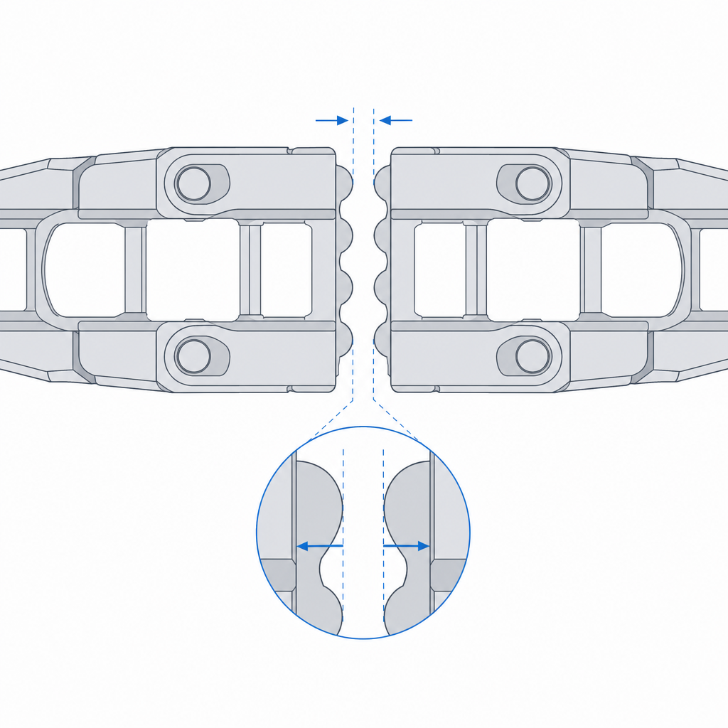
If you tune only one number in the whole part, make it this one. The spacing between each pair of facing surfaces is the gap that decides whether it articulates. But watch which dimension governs: what closes that gap isn't layer height, it's extrusion width. Each wall lays its bead toward the gap, and it's half that bead — not the layer — that intrudes into the spacing you drew. That's why a realistic clearance starts around 0.2 mm per face, almost regardless of whether you print at 0.12 or 0.28 mm, because with a typical bead of 0.4–0.45 mm each face eats on the order of 0.1 mm of gap per side before the chain ever leaves the plate.
Layer height does rule, but somewhere else: on the horizontal facing surfaces, the ones stacked in Z, where a gap thinner than one layer asks the machine for a vertical resolution it doesn't have. Think of this gap one facing face at a time, not as a single number for the whole assembly, the same way a pivot's clearance is computed per side and not per diameter: it's the same per-side accounting laid out in Tolerances for moving parts. And, as with any printed fit, the number on screen isn't the number in the part: the bead grows on both faces and eats into your spacing. That's why a "zero" clearance isn't a joint, it's a solid block.
| Material | Gap per face | Notes |
|---|---|---|
| PLA | 0.20–0.30 mm | a wide, forgiving window — the easy case |
| PETG | 0.30–0.40 mm | stickier and prone to welding; widen the gap and lower flow |
| TPU (flexible) | 0.30–0.45 mm | stringing and deformation; narrow window, test a coupon |
Lay it down: keep the joint in the XY plane
Orientation decides the quality of each joint face, because the printer doesn't reproduce a horizontal contour the same way it reproduces a vertical one. A surface defined by the perimeter in the XY plane — the contour the nozzle draws on each layer — comes out clean and to size: in the plane, your control over the nozzle's path is very fine. A horizontal contact face, by contrast, depends on bridging: the plastic has to cross the gap in the air with nothing underneath, and if the bead sags, it drops and closes the very space that was the whole point.
That's why the rule is to lay the chain down so the joint faces are defined by contours in XY wherever the geometry allows, and to reserve horizontal facing faces for short spans the machine can bridge without sagging. There's also a structural reason to lay it down, and it's the same anisotropy that governs any moving part: layers adhere poorly to each other, and the thin zone of a link — where its cross-section narrows to interlock — is exactly where you don't want a layer plane aligned with the load. Layer orientation for motion explains why that weak grain has to run with the load; in the chain it translates to the link flexing along the beads, not peeling them apart.
No supports, by design
A print-in-place chain carries no supports, and that's not a preference: it's a requirement. A support is plastic the machine deposits inside an overhang to hold it up, which you then expect to tear away. If that support lands inside the joint, you lose either way: either it welds the links because the support touches both faces at once, or it leaves a rough residue trapped in a gap you can't reach with any tool, and the chain comes out jammed. There's no way to clean the inside of a closed interlock.
The consequence is that the geometry is designed to hold itself up, and it's worth separating two limits that aren't the same. The overhangs of the inclined walls stay within the angle the material can hold without sagging — on the order of 45° from vertical in PLA. The roof of the joint gap, by contrast, isn't an overhang: it's a bridge, a horizontal unsupported span the nozzle crosses from wall to wall, and its limit isn't an angle but a bridgeable length, on the order of a few millimeters with good cooling. Keep that roof short and let the slicer bridge it; don't turn it into an open overhang that asks for support. A well-drawn chain is really an exercise in eliminating every overhang that would call for support, because the slicer doesn't distinguish a useful support from one that ruins the part: it deposits plastic wherever it sees air, and here the air is the function.
Calibration is part of the design
You can have the perfect clearance on screen and ruin it in the first layer. The first layer, the overall flow, and the cooling each decide how much real plastic comes out of the nozzle, and the first two both tend to close fine gaps. The squish of the first bead against the bed widens the first layers sideways and narrows the spacing right at the base of the chain, where the contact faces start; over-extrusion relative to the nominal bead — whether flow is set to 100% or 105% — thickens every bead and eats the gap along the whole interlock. On a normal part that's an ugly finish. On a print-in-place chain it's the difference between articulating and coming out solid.
There's a third control left, and in PLA it's perhaps the most decisive: layer cooling. The fan is what solidifies the bridge bead before it sags and closes the roof of the gap, and what keeps heat from building up in a narrow zone and softening the interface so it welds. With too little cooling, a clearance that's correct on paper comes out welded by pure retained heat. That's why calibrating flow, first layer, and fan isn't an optional prior step, it's part of designing the chain. A tenth of over-extrusion you wouldn't notice on a cube welds two links here. If you're coming from printing forgiving parts and you consider your flow dialed in, this is the part that will tell you the truth about your calibration: if the chain comes out rigid and the clearance was correct, it isn't the clearance — you're pushing out more plastic than you think.
Three failure modes, and what to do with each
A print-in-place chain fails in three ways, and you can read all three off the part as you peel it from the plate. The first is that the links come out welded: the chain is a rigid block, or it cracks and snaps when you try to bend it. The cause is insufficient clearance, over-extrusion, or poor cooling — all three close the gap — and it's corrected by opening the spacing, lowering flow, or raising the fan, almost never by touching anything else. The second is that the joint snaps on the first movement: the link gives way in its thin zone, clean and all at once, because the layers there were poorly adhered and the flexing peeled them apart. That's delamination, and you attack it with orientation — laying it down — and by reinforcing adhesion through design: more perimeters or more section in the narrow zone, and a slightly higher extrusion temperature overall. Be careful about lowering speed or raising heat only near the gap to "weld better" there: that same local heat softens the contact face and takes you straight to the first failure mode. The third is the opposite: that the chain falls apart, with links slipping out of the interlock because the clearance was excessive and the joint rattles loose until it disengages.
Knowing which of the three you have tells you exactly which number to move, and it's almost always just one. Welded: open the gap, lower flow, or raise the fan. Snapped: change its orientation and reinforce the thin section. Loose: close the gap. Don't change them all at once, or you'll learn nothing from the next print.
Beyond the visual effect, it earns its keep: the print-in-place chain is the best demonstration there is of a printer's tolerance control — if it comes out articulated, your machine is calibrated — and real applications follow: cable-carrier chains to guide hoses and wire bundles, flexible bracelets and straps, decorative transmissions, anything that has to bend in many directions without an axle. They all live or die by the same number, so before printing the chain it's worth pinning down your real gap with a coupon, just like any other printed fit, as explained in Tolerances for moving parts.