Dog clutch: engaging and disengaging rotation
A dog clutch doesn't grip: it interlocks. Instead of two discs pressed together that transmit torque by friction until one slips, it uses two rings of face teeth that mesh like interlaced fingers; from that moment the two shafts turn as one. There's no slipping, no friction torque to calculate, no surface to polish: either the teeth are engaged and transmit the full torque, or they're apart and transmit nothing. It's the most honest way to connect and disconnect rotation, and the least forgiving: all the smoothness a friction clutch provides through its slip, you have to build into the tooth geometry and into the moment you choose to bring the halves together.
Positive engagement: all or nothing
The difference from a friction clutch is one of kind, not of degree. A friction clutch transmits torque because two pressed surfaces resist sliding over one another, and that resistance has a ceiling: exceed the friction torque and it slips. That is at once its flaw and its virtue: it slips when you overload it, and that slip lets it gradually connect two shafts turning at different speeds.
The dog clutch has no such margin. The face teeth of one half drop into the gaps of the other, and the driving face of each tooth butts against its neighbor's flank. From there, transmitting torque means transmitting a contact force between two solid faces: there is nothing that can slide without something breaking. That's why the engagement is called positive. It transmits the torque in full, without the slip losses of friction and without heating up, right up to the limit where the tooth shears off. And for that same reason it doesn't modulate: there's no such thing as half-engagement. Connecting is dropping the teeth in; disconnecting is pulling them out. Between the two states there's no ramp, just a jump.
That binary nature is exactly what you want when you need slip-free transmission and a known shaft position, and exactly what you don't want when you need to ease into a start.
When it engages and when it clashes
The rule that governs the whole mechanism is this: a dog clutch engages well at low relative speed between the two halves, and badly — or not at all — when that relative speed is high. The kinematics explain it plainly. For a tooth to drop cleanly into its gap, the gap has to be waiting for it when the tip of the tooth reaches its plane. If the two rings turn at nearly the same speed, each tooth finds its gap open and slides in. If one ring turns much faster than the other, the teeth sweep past the gaps too quickly: a tooth tip reaches the plane when its gap has already passed and the next one isn't there yet; it strikes tip-first against the top of the opposing tooth and bounces. It doesn't engage: it hammers.
That's why a dog clutch is the right choice for connecting torque without slip losses when you can make the connection with the shafts stopped or nearly synchronized: a gearbox where you synchronize before selecting the gear, a selectable drive you engage at low speed, a lathe spindle. And it's the wrong choice for engaging two shafts at very different speeds on the fly, which is precisely the friction clutch's territory. Asking a dog clutch to engage across a large speed mismatch is asking it to eat its own teeth.
There's an opposite case worth flagging, because it's confusing: at exactly zero relative speed, the clutch still won't engage on its own if the teeth end up aligned tip-to-tip instead of tooth-to-gap. They sit butted tip-to-tip instead of dropping in. That's why clean engagement needs either a very slight relative speed that keeps sweeping the gaps open, or a guide chamfer that deflects the tip toward its place. Synchrony is not the same as alignment.
The tooth profile decides how it engages and how it holds
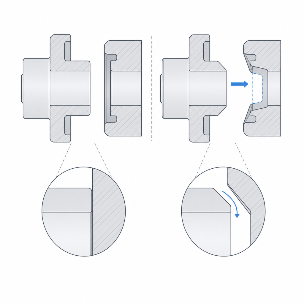
The whole character of the clutch lives in the shape of the tooth flank, and there's a trade-off you can't avoid. A straight-flanked tooth — faces parallel to the axis, perpendicular to the front face — engages firmly and transmits clean torque: the two driving faces meet square and the contact is flat against flat. But that same straight tooth is very hard to engage if there's any relative speed, because it has no geometry to guide the tip toward the gap: it either drops right into place or strikes edge-on.
A tooth with chamfered tips solves the engagement at the cost of firmness. If you bevel the tooth tip into a ramp, that ramp acts as a guide: when two teeth meet slightly out of phase, the ramp of one pushes the other sideways and the rings turn just enough for the tooth to drop into its gap. It engages far more easily while moving. The axial ejection component under torque comes not from that guide chamfer — which only acts during entry — but from any angle on the driving flank: if the faces transmitting the torque aren't perfectly parallel to the axis, the contact also pushes outward and tends to separate the two halves.
The next step is the asymmetric flank: one face straight and the opposite one ramped. This gives unidirectional behavior. In one direction of rotation the straight faces engage and the clutch transmits torque square; in the opposite direction the ramps meet, ride up over one another, and make one ring jump against the other, like a ratchet. That's what you want when torque should only be transmitted in one direction, and in the other you'd rather the mechanism slip than lock up. There's a consequence to watch for: for that ratchet to be able to jump, the ring has to be free to move axially on each tooth, so the unidirectional mode requires an elastic axial actuation — a spring that yields and returns — not a rigid retention that pins the tooth in. The tooth count and the flank angle are the two parameters you tune: with more teeth and shallower flanks, engagement is easier and more gradual; with fewer teeth and straighter flanks, it holds more torque but demands more synchrony to engage. As a starting point in FDM, 3 to 12 dogs and a 30°–45° guide chamfer cover most cases; fewer than three teeth concentrate too much torque on each flank.
| Flank profile | Engagement | Torque retention | Typical use |
|---|---|---|---|
| Straight (parallel to the axis) | Hard while moving | Firm; no geometric axial component, but needs retention under real load | Stopped or synchronized connection |
| Chamfered tips | Easy, self-guiding | Firm; the driving-flank angle adds axial ejection | Connection at low relative speed |
| Asymmetric (straight + ramp) | Easy in one direction | Transmits in one direction, jumps in the other (needs elastic actuation) | Unidirectional, ratchet-like coupling |
Printing the dogs in FDM
The print orientation is decided by the direction of the load, and in a dog clutch the critical point is the tooth root: the tooth works like a cantilever that bends at its base when the driving face transmits the torque. That bending loads the root fiber to the maximum, and in an FDM part what takes bending worst is the plane between layers. Print each half with the face teeth pointing up, so that the layers stack along the tooth and the root is crossed by continuous beads, not by the weak weld between layers. A tooth printed on its side, with the layer plane crossing the base, delaminates at that plane as soon as it takes real torque: it's the same orientation reasoning that governs any moving part, developed in Layer orientation for motion.
With the teeth pointing up, two details come up that are worth attention. The tips of the teeth come out stepped layer by layer if you leave them as sharp points; round or lightly chamfer them, not only so they guide the engagement better, but because a sharp printed tip is fragile and crumbles on first impact — and then it guides nothing. And the axial guide — the bushing, key, or profile the moving half slides along to go in and out — needs its real sliding clearance, not the nominal one: if you make it too tight, the clutch jams half-engaged and never fully engages or releases. Give it the gap of a sliding fit, on the order of 0.2–0.4 mm per side depending on your printer, as explained in Tolerances for moving parts.
Axial actuation and retention
A dog clutch doesn't actuate itself: you need something to push one half against the other to engage and pull them apart to disconnect, all in the axial direction. The classic part is a fork that wraps a groove on the moving half and slides it along its axis; depending on the application, that fork is moved by a cam, a lever, or a spring. A very useful arrangement is the return spring: the spring keeps the clutch permanently engaged, and the lever only works to disengage by overcoming the spring. That way the rest state is the transmitting state, and releasing the lever re-engages without your having to hold anything.
But the actuation that drives the teeth in isn't enough: you have to keep them there. This is one of the mechanism's most treacherous failure modes. A straight-flanked tooth seems to have no axial component, but under real torque, with the unavoidable slop of FDM and any slight deviation of the flank, the two halves tend to separate: the contact between faces generates a small force that pushes them outward, and if nothing holds them, the clutch disengages on its own precisely when it's carrying the most torque. The defense is an explicit axial retention: the same spring that keeps the engagement, or a small detent that demands deliberate effort to release. An undercut on the flank that makes the torque tend to pull the tooth in also retains it, but bear in mind two things before resorting to it: it turns the clutch into a coupling that no longer comes out freely, and with the teeth printed pointing up that undercut ends up as an internal overhang that prints badly or needs support. In FDM, the spring or the detent is usually the clean retention; the undercut, the last resort. Don't count on the guide's friction to hold: give it a retention designed to hold.
The failure modes, one by one
There are three clear ways to break this mechanism, and a fourth, subtler one; all four are prevented in the design. The first is tip clash: trying to engage at high relative speed, where the teeth hammer tip-against-tip instead of dropping into their gaps, and round over or break off in a few attempts. You avoid it by synchronizing before engaging and chamfering the tips so they guide instead of clash. The second is flank wear: every engagement rubs the faces against one another, and in plastic that rubbing rounds the flank cycle by cycle. And that rounding isn't harmless: it turns a straight flank into a de facto ramp, exactly the geometry that introduces the axial ejection component the straight tooth didn't have — that's why a worn clutch starts jumping under torque even though it held well at first. Here a more wear-resistant material helps, and above all not engaging more times than necessary. The third is the self-disengagement we've already seen: torque with no axial retention, halves that separate on their own.
The fourth ties into the craft of FDM: the tooth that shears at its root because the base ended up formed by a poor weld between layers. It's not that plastic is missing; it's that the plastic is badly oriented. That's why print orientation isn't a finishing detail in this mechanism, but the difference between a tooth that transmits the torque you calculated and one that comes apart along its weak plane at the first real load.
If you're building snaps around the clutch that should stay fixed rather than connect and disconnect, the reasoning about retention faces and non-releasing angles is in Snap-fits that won't release.