Oldham coupling: correcting parallel misalignment
You have two shafts that ought to be one, but they aren't: they come out of two separate parts, bolted together with screws that never land within microns, and their centers don't line up. A few tenths of a millimeter of parallel offset. Join them with a rigid coupling and that offset doesn't vanish—it turns into a bending load that pounds the bearings every revolution until they give. The Oldham coupling solves this almost by cheating: instead of fighting the eccentricity, it allows it and absorbs it by sliding. And it does so with no torsional backlash and at constant velocity, which is exactly what a rubber elastomeric coupling won't give you. The key is a central disc with two perpendicular keys, and on FDM almost the whole game is decided by the width of those keys.
How sliding absorbs the eccentricity
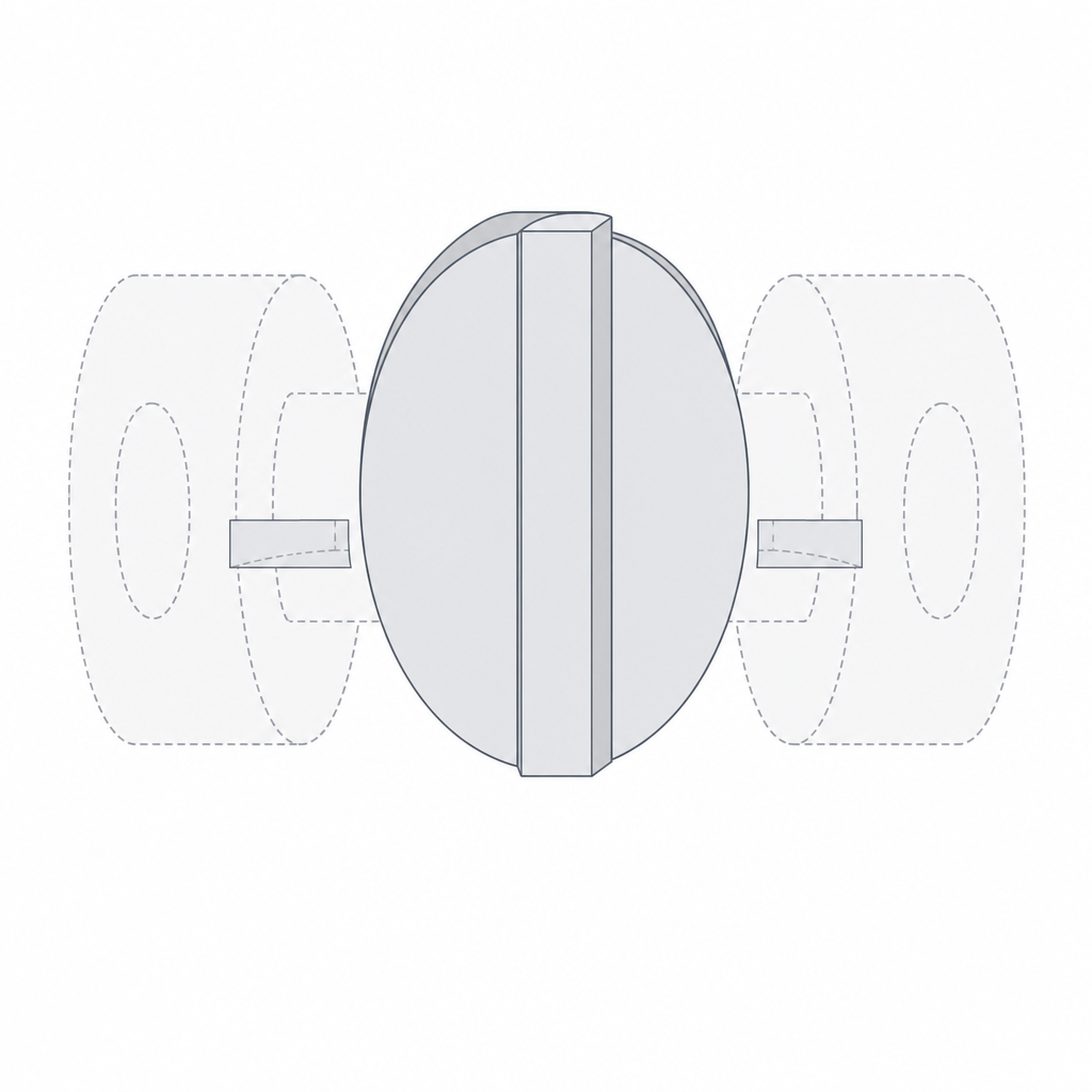
The Oldham has three parts: two hubs, one per shaft, and an intermediate disc between them. Each hub has a diametral slot. The disc carries two keys, one per face, and here is the key to the whole kinematics: the two keys are 90° apart. The key on one face seats in one hub's slot and slides along it; the key on the other face seats in the other hub's slot, perpendicular to the first, and slides along that one.
Think about what happens when the two shafts are offset and turning. The parallel offset between the centers can be decomposed into two perpendicular directions, and there are exactly two sliding degrees of freedom, one per key, also perpendicular to each other. Each key absorbs the component of the offset that falls along its slot. Because those two directions span the whole plane, between them they absorb any parallel offset, whatever its orientation. The price is that the central disc doesn't spin about a fixed axis: it traces a small orbit—its center travels around a circle of radius equal to half the offset—while it transmits torque. Each key, for its part, travels back and forth within its slot a peak-to-peak distance equal to the full offset on every revolution.
What matters about that orbit is what it does not do. It introduces no bending into the shafts, because the keys transmit only tangential force—the force that produces torque—and leave the radial sliding free. That's why the bearings on each shaft never see the side load from the offset: the disc takes it. And because the drive is by direct key-against-slot contact, with no elastic element in between, the output angular velocity is constant and equal to the input at every instant. That combination—correct parallel offset, don't load the bearings, and hold constant velocity—is the Oldham's signature, and the reason it exists when simpler couplings are already on the shelf.
There's a nuance worth nailing down before going on: the ideal Oldham has no torsional backlash, but the printed Oldham has it from the very first turn, set by the sliding clearance between key and slot. That clearance is backlash from minute zero—the key can move in the torque direction before it touches the opposite flank—and it grows with wear. Don't chase absolute zero: chase the minimum clearance that still slides without binding.
When to use the Oldham and when not
The Oldham solves one specific problem: parallel shafts with an offset you can't eliminate. A printed assembly that never quite aligns, two brackets bolted up separately, thermal expansion that shifts the centers in service. If on top of that you need to hold constant velocity and tolerate little backlash—an encoder, a positioning axis, anything where play shows up—the Oldham is the right answer, as long as you accept the starting backlash that the printed clearance imposes and calibrate it as tight as you can.
It helps to place it next to its neighbor, the jaw (spider) coupling. Both tolerate misalignment, but not the same kind. The Oldham is built for parallel offset: it absorbs it with room to spare, far more than the jaw coupling does. In exchange, it tolerates angular misalignment poorly—shafts that aren't parallel, that form a small angle to each other; in that case the jaw coupling, with its elastic element, behaves better. The rule is direct: if your shafts are parallel but offset, use an Oldham; if they're tilted relative to one another, look elsewhere. And if what you have is a genuinely large angle, neither one will do: that's a job for a universal joint.
One last condition of operating range. The Oldham is a low-to-medium-speed coupling. As it orbits, the disc oscillates laterally every revolution, and that oscillation generates inertial forces that grow with the square of the rpm and with the offset. A light plastic disc damps them down compared with a metal one, but at high speed they vibrate the assembly and accelerate wear of the keys. If you need to spin fast, this is not your coupling.
The disc is the sacrificial part: design it to wear
In a printed Oldham there's a hierarchy of sacrifice worth respecting on purpose. The keys of the central disc slide in their slots every revolution, traveling out and back a distance equal to the offset; that continuous rubbing means the disc wears first, and that's good: it's the part that protects the others. Design it as a consumable. It's cheap to reprint—it's the small part, with no shaft bore whose tolerances you have to dial in—and when the keys have worn enough backlash to be noticeable, you swap only that disc and the coupling is back to its original state. The hubs, which do carry the joint to the shaft and cost more to iterate, stay untouched.
That same sacrificial logic has a second face: torque. The printed key is the thinnest link in the chain, and under excessive torque it's what breaks. Take that as a design property, not a defect: the disc is your mechanical fuse. If something jams further down the drivetrain, you'd rather snap a key on a disc you reprint in minutes, not hours, than blow up a shaft, a bearing, or the motor.
But "the disc is the fuse" is not an intention, it's a calculation. The breaking torque is set by the cross-sectional area of the key at its root—width times height at the base, perimeters and infill included—and by the layer orientation. If you want it to break later, thicken the base of the key or raise perimeters; if you want it to break sooner to protect something expensive downstream, thin it. And in every case, leave a fillet at the foot of the key: a sharp edge there concentrates stress and breaks early, well below the torque you'd calculated.
For the disc to wear clean and not bind, the material matters, and here's a nuance that gets overlooked. PETG is tough, but PETG sliding against PETG tends to gall (galling, stick-slip): two surfaces of the same soft plastic stick instead of sliding. If you're going to use PETG, the best move is to pair different materials—disc in one material, hubs in another—or reach for a plastic with better friction behavior for the sliding part (a dry PLA, or Nylon or POM if you have them). The goal is a pair of surfaces that slides, not one that bites.
The keys: width, clearance, and layer orientation
This is where the coupling is won or lost. The key and its slot form a sliding fit, and everything you know about printed clearances applies here with a vengeance, because the error isn't spread around a diameter: it lands entirely on the width of the key and the width of the slot. Aim for a sliding clearance on the order of 0.1 to 0.2 mm per side between the key flank and the slot flank—the value of a fit that slides freely, not one that positions—and remember that this gap is per side, so your nozzle and your calibration decide where you land within the range. Be clear about the cost: that same gap is the coupling's starting backlash, so if your application is precision, drop to the tight end of the range and accept calibrating several times. The full reasoning for why it's counted per side, and how much your printer will eat, is in Tolerances for moving parts.
How you split the gap works in your favor if you set it up right. Leave the hub slot at its nominal size and create the clearance by thinning the width of the disc key, which is the cheap part and the one you'll reprint anyway. That way, if it goes in tight, you adjust only the disc. Too tight and the coupling binds: the key won't slide, the offset isn't absorbed, and you're back to a rigid joint that loads the bearings—the silent failure: the coupling looks assembled, but it has stopped doing its job. Too loose and the starting backlash is already excessive, without even waiting for wear.
There are two more clearances besides the width that decide whether the assembly works once built. The first is axial: the key must not touch the bottom of the slot. Leave a gap between the tip of the key and the bottom; if it bottoms out, it transmits axial load, pushes the shafts together, and binds just like a tight width fit. The second is the engagement overlap: the key has to stay inside its slot when the disc orbits at maximum offset. That overlap is what really limits how much offset you can tolerate—the Oldham absorbs "generously," yes, but only up to the point where the key doesn't slip out of the slot. Size the length of the key and the length of the slot so that, at the worst point of the orbit, they stay engaged with margin.
Print orientation decides the quality of the sliding flanks and the strength of the keys. Print each hub with its slots in the XY plane, laid flat on the bed, so the slot walls print as smooth, vertical perimeters and not as a stair-stepped surface. A slot printed upright ends up with stepped flanks, and that's friction and uneven wear from the very first turn.
The disc keys are thornier, and here there's a trade-off worth not hiding. The disc prints naturally flat on the bed—that's the convenient way for its two key faces—but then the layers end up perpendicular to the axis of rotation and the tangential force of the torque shears between layers, which is the worst case for delamination. And because the two keys are perpendicular to each other, there's no orientation that puts both of them along the bead: one will always work in shear. There's no clean solution, only mitigation: thicken the key section at its root, raise perimeters, leave the fillet at the foot, and if the torque demands it, consider printing the disc on edge, accepting the supports and the worse finish on one face. The reason for that anisotropy, and how to read it part by part, is in Layer orientation for motion.
| Parameter | Starting value | Why |
|---|---|---|
| Key/slot clearance | 0.1–0.2 mm per side (calibrate) | slides free; that gap is also the starting backlash |
| Splitting the gap | thin the key width | the disc is the cheap, consumable part |
| Axial clearance | gap between key tip and slot bottom | if it bottoms out, axial load and binding |
| Engagement overlap | key inside the slot at maximum offset | limits the offset you can tolerate |
| Hub orientation | slots in XY (laid flat) | smooth flanks, not stepped, so they slide |
| Key root | generous section + fillet | sets the breaking torque; avoids early fracture |
| Sliding material | a pair of different surfaces; avoid PETG–PETG | the same soft plastic galls |
| Hub–shaft joint | setscrew / keyway / non-round shaft | friction on a round hole won't transmit torque |
The shaft joint: the point where torque is lost
The Oldham can be perfect and still slip, because there's a link outside the coupling that always gets overlooked: how each hub grips its shaft. A printed round hole around a round shaft won't transmit torque reliably, no matter how hard you clamp it. The friction of a smooth printed cylinder is scarce and, worse, decays over time: the loaded plastic creeps slowly, releases the pressure that was clamping it, and the hub ends up spinning free on the shaft. It's the same problem as any rigid hub-shaft joint, and it's solved the same way.
You need a positive lock, not friction. A setscrew biting against a milled flat or a relief on the shaft; a keyway, slot and key transmitting by form; or simply a non-round shaft—a hexagon, a square, a D—seated in a hole of the same profile, which prevents rotation by geometry without relying on any clamping force. Any of the three turns the joint into a reliable torque transmission. If you're going to drop a metal setscrew or a threaded insert into the hub, plan its pocket from the model; how to embed that hardware without cracking the part is in Embedded hardware: magnets, bearings, and inserts.
When the three elements are sorted—keys with their clearance, hubs well oriented, and a positive joint to each shaft—the Oldham does its job quietly for a long time, and the day the backlash grows, you reprint the disc and carry on. If your problem isn't parallel offset but shafts that come out tilted relative to one another, that's another coupling and another set of kinematics: start by measuring whether your misalignment is parallel or angular before you commit to this geometry.