Kerf bending: cut patterns that bend the rigid
Take a plate that won't bend — rigid, flat, the kind that snaps before it yields — cut a lattice of slots into it, and suddenly it rolls up. You haven't changed the material: it's the same stiff plastic. You've changed the geometry, and that's enough. The flexibility of a kerf pattern doesn't live in the polymer but in what you remove: the cuts leave a grid of thin bridges, each one bends a hair, and all of them together add up to the curvature the whole plate couldn't deliver. It's the laser-cutter-on-plywood trick carried over to FDM (fused deposition modeling), and, like everything that hands a function over to geometry, it hinges on a few tenths of a millimeter of pitch and bridge width that almost nobody stops to work out.
Flexibility belongs to the pattern, not the material
A solid plate won't bend because, to curve, its outer fiber would have to stretch a lot and its inner fiber compress just as much: the thicker the plate, the farther those fibers sit from the neutral plane and the more strain any curvature demands. PLA tolerates little stretch before breaking — somewhere between 2 and 4% in tension on a printed part, with the brittle formulations toward the low end — so it reaches its limit at a still very open bend radius and snaps before it truly bends. That's the physical wall the kerf routes around.
What a kerf pattern does is break that one impossible bend into many tiny bends. Each cut interrupts the continuity of the plate and leaves a narrow bridge of material beside it; when you curve the whole assembly, the strain no longer spreads through the full thickness of a thick plate but concentrates in those bridges, which are thin and therefore flex with little strain in their outer fiber. The plate rolls up because each bridge gives a degree or two, and there are dozens of bridges in series. The global stiffness collapses, but the local strain of each flexor stays below the material's limit. That's the whole idea: you never ask any point in the plastic for more stretch than it can give; you ask a little of many places.
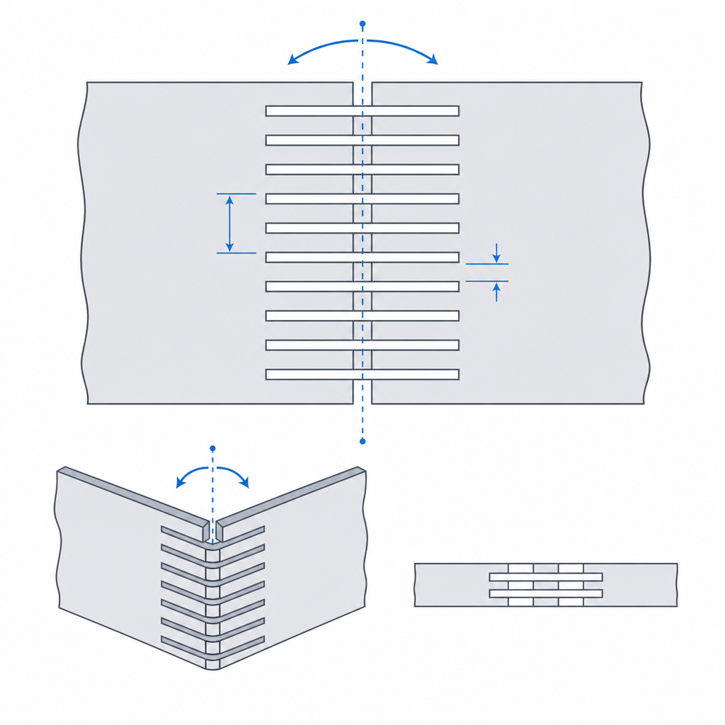
It's worth being clear about the consequence before you draw a single cut: the pattern is only flexible in one direction and one sense of curvature. A straight lattice hinge of alternating parallel cuts bends around the axis perpendicular to the cuts and is as stiff as ever in any other direction. And it bends freely toward one side — the one that opens the slots — and much worse toward the other, where the lips of each cut close and butt against one another: the geometry runs into itself. That isn't a defect, it's the tool. You decide where it bends by orienting the cuts, and you orient the pattern so that the sense in which the slots open matches the sense in which you're going to fold.
Pitch governs the minimum radius and the force
Two dimensions govern the whole behavior, and they pull in opposite directions. The pattern pitch — how often the cut repeats — and the bridge width left between consecutive cuts set both the minimum bend radius and the stiffness you keep.
The logic is direct. The more cuts you fit per unit length, the more bridges you spread the total curvature across, so each one bends less: the minimum achievable radius tightens. And the thinner you make each bridge, the less strain its outer fiber suffers for a given bend angle. It's the same beam physics as any flexor: strain grows with the thickness of the flexing section. So a thin bridge tolerates tighter curves without cracking. Up to here, everything pushes toward denser cuts and thinner bridges.
The price is force. Those same thin bridges that bend without trouble are the ones holding the plate together, and a thin bridge holds little: it resists less in tension, less in bending outside its weak direction, and less in fatigue. Flexibility and strength are the same lever with two ends: you thin the bridge and gain curvature in exchange for robustness; you thicken it and recover stiffness while losing radius. There's no universal sweet spot, there's the point your part needs — a target bend radius on one side, a load to carry on the other — and the pitch is computed from those two constraints, not picked to taste.
Print with the bridges lying in their strong plane
Here FDM extracts its toll, the usual one: the part is anisotropic, strong along the beads and weak between layers, where it's held only by the adhesion of one layer to the next. A kerf bridge is a very thin flexor, and a very thin flexor is exactly where anisotropy decides whether the part lives or delaminates at the first bend.
The rule is to lay the plate flat on the bed, with the cuts and bridges in the XY plane and the layers stacked in Z, and orient the bend around an axis contained in that XY plane. That way each bridge flexes along its beads: the bending is absorbed by the beads in tension and compression along their axis, and the bond between layers is barely called on. If instead you let the layer line cross the bridge in the direction it's going to bend, every flex pulls directly on the weld between layers and the bridge opens like a clean crack, almost always within the first few cycles.
Because the bridges are thin, the perimeter count is nearly everything. A bridge a single bead wide comes out as a single perimeter, with no core and no redundancy: well oriented it flexes beautifully, but any local extrusion defect — a layer with poor adhesion, a moment of underextrusion — turns it into a breaking point with no warning. For parts that will accumulate cycles, fix it as robust practice to use at least two perimeters — two bead widths — and leave the single perimeter as an explicitly risky edge case, not the norm. In any case, give the bridge a thickness the slicer resolves as a full, continuous perimeter, not as scattered infill, which in such a narrow section barely works at all.
And watch out for out-of-plane load. These patterns are flexible on their bend axis but fragile in torsion and against any push perpendicular to the bed, because there you really do put the Z bond between layers in tension. Few layers plus out-of-plane load is the recipe for delamination; if the part will see torsion in service, rethink the pattern or thicken it.
Choose the pattern by where it has to bend
There isn't one kerf pattern, there's a family, and you pick by the kinematics of the bend you're after.
The straight lattice hinge — rows of parallel cuts, staggered like brick coursing so that no cut leaves a straight fracture path — bends around a single line. It's what you want to fold a plate on one axis: a lid that swings down, a housing that closes over an edge. It spreads the bend across all the rows and behaves like a hinge distributed along a straight line.
When you need curvature in two directions at once — wrapping a plate onto a doubly curved surface, dressing a cylinder or an organic shape — the parallel-cut pattern isn't enough, because it only gives in one axis. That's where lattice meshes come in: grids of bridges that let the material flex in several directions, at the cost of more fragility, because bending in two directions forces you to loosen the material in both. The practical rule is not to ask a pattern for more degrees of freedom than the part needs: every bend direction you open up is stiffness and strength you give away. If you only bend on one line, use the one-line pattern.
| What you want | Pattern | In exchange for |
|---|---|---|
| Fold on one axis (lid, long hinge) | Straight lattice hinge, staggered cuts | Rigid in every other direction |
| Wrap onto a cylinder | Straight lattice hinge, cuts perpendicular to the wrap direction | Cylinder radius ≥ the pattern's minimum radius, or immediate failure |
| Curve in two directions | Lattice mesh | Less strength, more global fragility |
Where it breaks: bridge fatigue and live corners
A kerf pattern fails in two ways, and both are avoidable if you name them before you print.
The first is bridge fatigue from bending it over and over. Each bridge is a flexor that stretches and compresses its outer fiber on every cycle; even with the strain below the static break limit, the material degrades with each bend and eventually breaks from accumulation. PLA is the worst at this — stiff and brittle, it fatigues early — while PETG and, above all, tough materials survive many more cycles with the same pattern. And there's a factor almost nobody accounts for: in a thermoplastic, fatigue depends on the speed and temperature of the bend. The behavior is viscoelastic, so bending fast or cold embrittles, and a bridge that survives a slow flex can snap if you bend it abruptly. If you exceed the minimum radius the pitch allows, moreover, fatigue stops being progressive and becomes immediate failure: you're asking the bridge's outer fiber for more stretch than it gives, and it snaps on the spot. The minimum radius isn't advice, it's a wall; design the working radius with margin over it — on the order of 1.5 to 2 times the static minimum radius — to separate static failure from fatigue life.
The second, and the one that quietly claims the most lives, is the live corners at the ends of the cuts. The end of each slot is a sharp re-entrant, and a sharp re-entrant is a stress concentrator: the strain you thought was spread across the whole bridge spikes locally at that tip, and the crack starts right there, on the first cycle, even if the rest of the bridge was amply sized. The defense is cheap and rarely modeled: round the tips of the cuts. A radius at the end of each slot spreads the stress peak over a curve instead of pinning it at a vertex, and that multiplies the pattern's fatigue life. It's the same logic as the fillet radius at the root of any flexor: a live corner where stress concentrates is a fracture line you drew without meaning to.
When kerf beats a concentrated hinge
The kerf pattern shines exactly where a classic living hinge breaks. A concentrated living hinge puts all the flexing into a single thin strip; it works for one clean bend axis and a couple of rigid parts, but it forces the material to bend a lot in very little space, and as soon as the radius tightens or the cycles add up, that single strip is the point that fails. Kerf does the opposite: it spreads the same total bend across many flexors, so none of them takes the full punishment. Where a concentrated living hinge would crack, a distributed hinge survives because each bridge works with margin to spare.
That's why kerf is the answer for lids that roll up instead of swinging open, for pulling curved housings out of a flat plate, and for any joint that has to bend along a wide band rather than a line. It isn't a universal substitute for the hinge: if what you want is a precise, low-travel pivot axis, other solutions give you better centering. But when the problem is turning the rigid into something that curves at a controlled radius, with no pins and no assembly, kerf is the geometry that solves it.
The part comes off the bed lying flat precisely to gain interlayer strength, and you curve it afterward: that decision to orient the bend relative to the layers is the same one that governs any printed flexor, and you have it laid out in full in Layer orientation for motion.