Trammel of Archimedes: drawing an ellipse
Drop two sliders into a pair of slots that cross at a right angle, link them with a rigid arm, and a point on that arm—chosen on the line joining the two sliders—will trace a perfect ellipse as you move it. Not an approximate ellipse, not an oval that comes close: an exact ellipse, defined by the geometry, with no cams and no templates. It's one of those mechanisms that looks like a trick and is pure kinematics, and understanding it hands you, all at once, a curve tracer, a hypnotic toy, and a lesson in how two coupled straight motions become one curved one. The catch: printed in FDM, the whole mechanism lives or dies by one sliding clearance — and you have to nail it.
Why an arm between two slots draws an ellipse
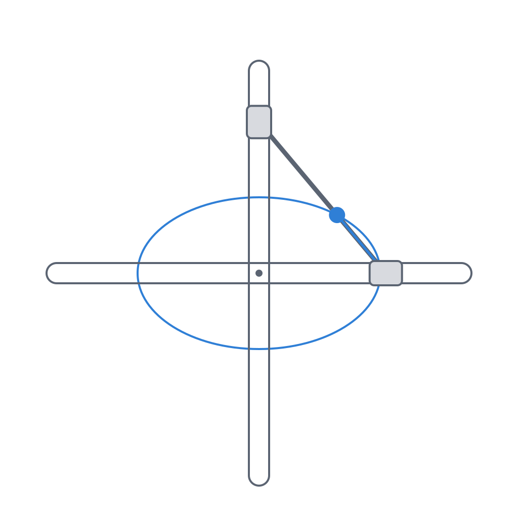
The kinematics is simpler than the result suggests. You have two straight, perpendicular guides—call them the X axis and the Y axis—and two sliders, one trapped in each guide, so that the first can only move along X and the second only along Y. A rigid arm joins the two sliders. Since both are bound to their respective lines but the arm between them keeps a fixed length, pushing one drags the other: as one slider approaches the crossing, the other moves away, and vice versa. Two straight-line reciprocations, coupled by the rigidity of the arm.
Now fix a tracing point on the very line that joins the two sliders—that's the condition that makes it work—at a distance p from the slider that runs along X and a distance q from the one that runs along Y. That point traces an ellipse whose semi-axes are exactly q and p, with the distances swapped: the semi-axis along the X axis is governed by the Y slider, and conversely. Here's why. The position of each slider along its guide governs one of the point's two coordinates, and since the angle of the arm sweeps through the full rotation as the mechanism moves, one coordinate varies as the cosine of that angle and the other as the sine. A point whose two coordinates are q·cos θ and p·sin θ describes, by definition, an ellipse with semi-axes q and p. There is no approximation at any step: the ellipse is the algebraic consequence of the geometric constraint, as long as the point lies on that line. A point off the line also traces an ellipse, but a rotated one, not aligned with the guides.
Two limiting cases fall out of this, and they're worth keeping in mind. If you put the tracing point right on top of one of the sliders, its distance to that slider is zero, one of the semi-axes vanishes, and the "ellipse" degenerates into a straight segment: that slider, of course, only moves along its slot. And if you put it at the midpoint of the arm, equidistant from the two sliders, p and q are equal and the ellipse becomes a circle of radius equal to half the arm—that is, half the distance between the sliders. That midpoint sweeping a perfect circle, generated by nothing but two straight slides, is the kinematic version of the old result of La Hire's circles: a line whose ends slide along two perpendicular axes makes any point on it describe an ellipse, and the center, a circle.
What it's good for
Historically it's a drafting tool: the ellipsograph, the compass that traces ellipses where an ordinary compass only gives circles. You fix the two slots to a base, mount a pencil at the point on the arm set by the semi-axes you want, and as the arm turns the pencil sweeps the entire ellipse. Changing the ellipse means moving the pencil to another point on the arm or readjusting the sliders; the family of ellipses a single trammel can trace is exactly the set of all the points on its arm.
Its second life is as a kinematic toy. Built with two crossed sliders and a crank that turns the arm, the trammel is the classic do-nothing machine: it spins indefinitely, produces no useful work, and is impossible to stop watching, precisely because the eye never quite believes that two straight slides are enough for that interlocked motion. As a teaching piece it's priceless: it shows, without a single equation, that curved motion needs no curved part, that it's enough to couple two straight-line motions with the right phase. And as a mechanical generator, it gives you elliptical motion—or circular, at the midpoint—out of straight guides, without cutting a cam or fitting a gear. It earns its place wherever you need that motion without machining a profile.
Sliding clearance: the only number that matters
This is where the trammel stops being textbook geometry and becomes an FDM part with its own failure modes. The whole mechanism rests on four sliding contacts: each slider against the two walls of its slot. The ellipse will only be clean if those slides are smooth and even, and that depends entirely on the lateral clearance between slider and slot.
The trouble is that this clearance has two ways to ruin the part, one at each extreme. If you leave too little gap, the slider seizes: remember that a printed slot prints narrower than its nominal dimension because the perimeter bead bites inward, so a clearance of zero on screen is interference in the part, and the slider won't go in, or goes in only to jam. If you leave too much gap, the slider rattles inside the slot, and that lateral play translates directly into tracing error: the point that should follow the ellipse jitters, the curve comes out thick and jittery, and in the midpoint case the circle no longer closes cleanly. The clearance is, without exaggeration, the parameter that decides whether the trammel traces fine or seizes.
As a starting value for a print-in-place trammel—printed already assembled, with no assembly step—a lateral clearance on the order of 0.15 mm per side between slider and slot wall works: a clean gap so it breaks free without sticking, but without the wobble a tracer won't forgive. If you print it as separate pieces and assemble by hand you can tighten toward 0.10–0.15 mm per side, because you control the fit at assembly and don't depend on the part releasing itself. But no number transfers blindly: the real gap is set by your printer with your material, and the honest way to know it is to measure it once with a coupon, as explained in Tolerances for parts that move. Nail that number before you print the whole mechanism.
| Assembly | Clearance/side (effective) | What you're after |
|---|---|---|
| Print-in-place (printed assembled) | 0.15 mm | breaks free and slides without sticking |
| Separate pieces, hand assembly | 0.10–0.15 mm | remove wobble, firm slide |
| Too little (< 0.08 mm) | — | seizes: the slot prints narrow |
| Too much (> 0.25 mm) | — | rattles: distorts the ellipse |
The column is effective clearance, what's left in the part after the perimeter narrows it. On the model you'll have to draw something wider to reach it; how much wider is told by your tolerance coupon, not by a table.
Print the plane of motion flat
Print orientation is no aesthetic detail in this part: it decides whether friction is even or uneven, and whether the sliders release or fuse together. Print the slot plate flat on the bed, with the slots running in the XY plane. That way the walls each slider slides against are vertical faces made of stacked perimeters, with far more even friction along the whole travel.
If instead you orient the part so a slider slides across the layer planes—rising or falling relative to the bed—you incur the staircase effect: the wall stops being smooth and becomes a succession of steps the height of the layer, and the slider has to climb each one. Friction shoots up and turns uneven, with catches—exactly what ruins the smooth tracing of an ellipse. It's the same logic as Layer orientation for sliding motion: surfaces that slide want the beads running with the motion, not across it.
That flat orientation solves the side walls, but it opens a second front. The slider needs to be captured in the slot without escaping upward, and that calls for a lip or a captive nub that holds it in Z. With the plate lying flat, that lip prints as an overhang or bridge over the slot opening, and its clearance isn't the lateral wall one: it's a layer-to-layer clearance, which finishes rougher and usually needs a bit more gap to break loose. Treat it separately. And watch the base: in print-in-place, the first layers of the slider and the slot sit so close to the bed that elephant's foot and the over-squish of layer one tend to fuse them together, regardless of the lateral clearance you drew. It's the most common cause of a print-in-place that won't release. Compensate by calibrating elephant's foot or leaving a bit more gap in the first few tenths of height.
How it fails and how you'll spot it
It pays to know in advance where the tracing breaks down, because each symptom points to a specific cause. The most immediate failure is the slider that seizes: either from a lack of lateral clearance—the slot ended up narrower than you drew—or from layer staircasing if you printed it with the plane of motion poorly oriented, or from the first layers welding against the bed. You'll spot it the moment you free the part: the arm won't run, or runs in jerks. The cure is to open the clearance, reorient, or calibrate elephant's foot—never force the slide, which only speeds up wear.
The second failure is the deformed ellipse: the mechanism moves, but the curve comes out unevenly oval, thickened, or visibly trembling. That's excess play in the sliders, that wobble, amplified at the tracing point. The curve, in a sense, is drawing the leftover clearance for you.
And the third is the long-term one: wear of the slot walls after many cycles. Plastic-on-plastic sliding gradually polishes and widens the slot, so a trammel that started tracing fine ends up with too much clearance and a shaky line through sheer use. There's no magic that fully prevents it in FDM. You mitigate it with slot walls of several solid perimeters (three or four) so they have material to spend, and by accepting that a tracer meant to turn thousands of revolutions is a candidate for a more wear-resistant material or a couple of drops of dry lubricant.
If these mechanisms that turn a rotation or a reciprocation into a precise path without cams have caught your curiosity, the natural next step is to understand how you pick and tune the clearance that decided everything here. Tolerances for parts that move is where that number stops being a guess and starts coming out of your own printer.