Walking legs: Klann and Jansen linkages
A wheel has it easy: it spins and it rolls forward. A leg does not. A leg has to touch the ground, stay planted on it while the body passes overhead—so that it moves backward relative to the body even though it isn't moving relative to the ground—then hold the same height so the body doesn't bounce, lift off, fly back through the air, and set down again at the same point in the cycle. Doing that with a motor that only knows how to spin seems to demand joints controlled one by one, and for a century that's how it was solved. The leg linkage is the pure mechanical answer: a crank that turns without stopping and a network of rigid bars that translates that rotation into a footstep. No sensors, no control, no intelligence beyond what is frozen into the lengths of the bars. And that's exactly what makes it hard to print: the entire gait lives in a handful of dimensions that FDM tends to corrupt.
The foot path is the whole mechanism
The only thing that matters about a leg linkage is the path a specific point—the foot—traces as the crank makes one full turn. That point belongs neither to the crank nor to any bar anchored to the frame: it belongs to a coupler link, a bar that floats, connected to two others, with no fixed point of its own. A coupler neither rotates nor swings in any simple way; each of its points traces a different closed curve, sometimes surprisingly intricate, and that family of coupler curves is the raw material from which any motion mechanism is made. Designing a leg means choosing the bar lengths until one point on that coupler traces exactly the curve that walks.
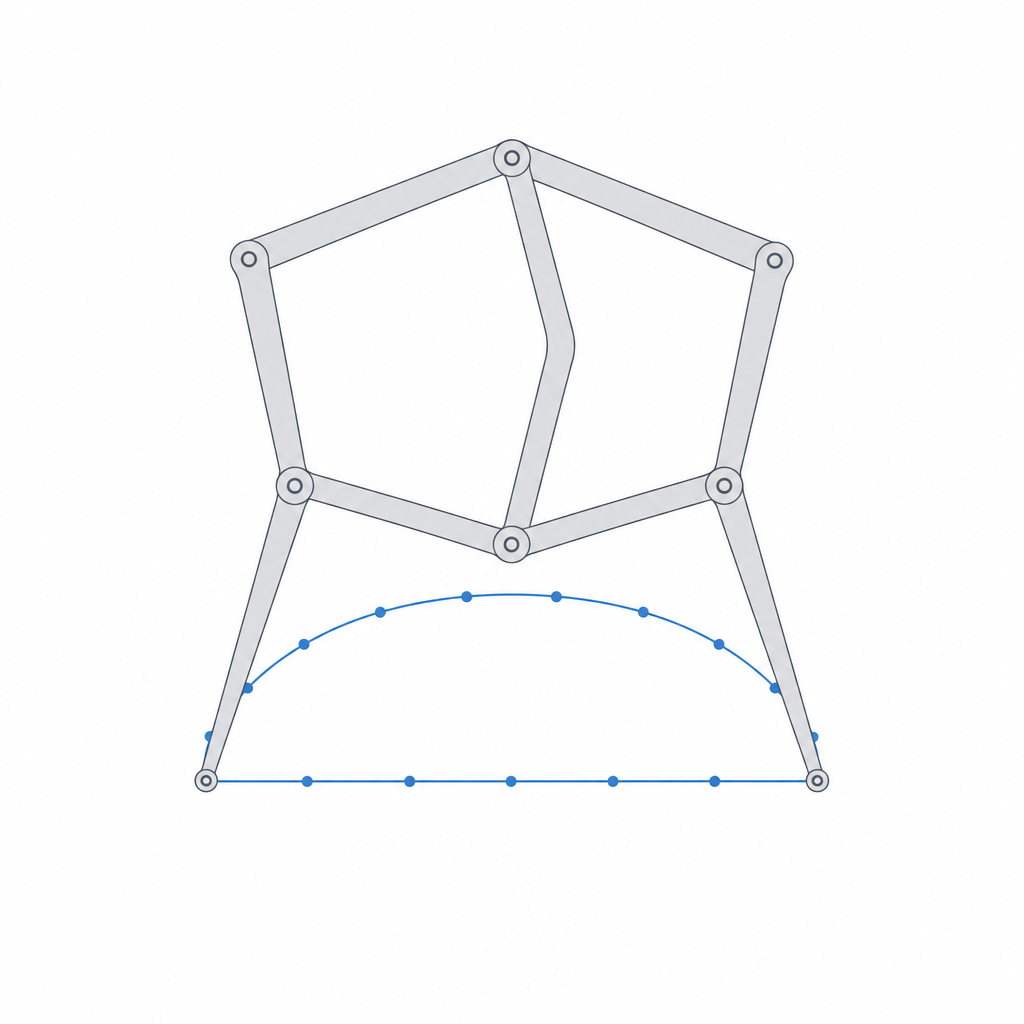
And what shape is a curve that walks? Two clearly distinct segments. Below, a nearly straight, nearly horizontal stretch of curve: this is the stance phase. While the foot travels that segment it is planted on the ground, and because its contact point advances in a straight line at constant height relative to the body, it drives the body forward without lifting it or letting it drop. If that segment weren't flat, the body would bounce up and down at every step; if it weren't straight, the foot would scrape sideways and slip. Above, a broad arc: this is the swing phase, the return through the air. The foot lifts off cleanly, flies backward relative to the body—forward relative to the ground—and drops back down to the start of stance. One turn of the crank, one step. The foot path doesn't represent the mechanism: the foot path is the mechanism, and everything else is bars that exist solely to produce it.
The Klann linkage achieves this with six moving links—a crank, two rockers anchored to the frame, two couplers, and the leg itself; the Jansen, with eleven bars per leg in two coupled loops. More bars give a more faithful curve—a flatter stance, a cleaner liftoff—in exchange for more joints, which is exactly where FDM takes its toll.
Why the sacred numbers are non-negotiable
Theo Jansen didn't derive the lengths of his eleven bars from a closed-form formula: he searched for them with a genetic algorithm he left running for months, evaluating millions of combinations by the quality of the footstep they produced. The result is a set of eleven lengths he calls the sacred numbers, and the word isn't romantic—it's literal in its consequences: they are a narrow optimum. Those specific proportions are what make the stance segment come out flat and level and the foot lift with enough clearance to clear the terrain on the return.
What's worth understanding before you start printing is that this optimum is fragile under change. Alter one bar a little and the foot path deforms: the stance segment stops being flat and starts to bulge, the foot tilts, or the return arc flattens and the foot grazes the ground during what should be free flight. It isn't that the mechanism fails all at once; it limps, and it limps in proportion to how far you've strayed. There is also a threshold sharper than the gradual limp: certain length combinations make the crank unable to complete a full turn—it stops satisfying the Grashof rotatability condition—and the mechanism jams partway through a revolution instead of walking. It isn't enough for the curve to come out pretty: the crank has to be able to rotate a full 360°.
This has a direct, hard implication for anyone printing it: your bar lengths are critical dimensions, not approximate ones. The distance that truly governs the gait isn't the outer length of the bar you see, but the distance between the centers of the two pivots of each link—its effective kinematic length. If, through a tolerance error, a hole ends up off-center or an axle prints too thick and seats to one side within its clearance, you've changed that center-to-center distance and shifted the sacred number without meaning to. That's why a leg linkage punishes imprecision far more than a rougher mechanism does: it doesn't forgive deviations you wouldn't even notice on a hinge.
One motor, several legs, one continuous gait
A single leg doesn't walk: during its swing phase it isn't touching the ground, and if it were the only thing holding up the body, the body would fall. Continuous locomotion comes from phasing several legs on the same crank. The temptation is to think that two legs at 180° are enough—one in stance while the other swings—but they aren't: the stance phase rarely occupies exactly half the cycle, so with only two legs there are moments when neither is pushing, and on a single axis two legs give no lateral stability, so the body tips over. That's why a steady gait starts at three or four legs per side, spread across staggered phases: at every instant several feet are in contact and the body advances without bouncing or running out of support. Jansen's Strandbeest takes this idea to the extreme: rows of phased legs driven by a single crankshaft, so that one motor—or one gust of wind—produces a fluid, continuous gait.
This is what makes the leg linkage attractive against wheels: it advances over rough terrain without needing suspension, because each foot sets down and lifts along its arc, clearing obstacles that would stop a wheel of its size. Walking robots and toys, simple all-terrain platforms, demonstrations that a network of bars generates locomotion with no electronics whatsoever: that's where it shines. But the phasing, its kinematic virtue, is also an assembly demand. The cranks have to be keyed at their correct angles and the assembly has to be able to cross the dead points—the positions where crank and connecting rod line up and the crank's torque no longer produces useful motion. With enough well-spread legs, while one crosses its dead point another is fully under load and carries the assembly past it; with the phasing done wrong, several legs can coincide at a dead point and the mechanism locks, unable to start.
Why many pivots punish FDM
Here is the real battlefield. A four-bar has four pivots; a Jansen leg runs to about a dozen joints, and a complete machine, to dozens. And pivot clearances accumulate along the chain. Each joint has its small play—that gap between axle and hole without which the joint wouldn't turn—and in a chain of bars those plays link up along the force path, so the foot inherits the play of every joint upstream. In the worst case, when all the plays line up, they simply add; in the typical case, being random and independent, they grow more slowly—on the order of the square root of the joint count—but they don't cancel. And it isn't a straight sum of millimeters: each joint's play is amplified by the lever arm that separates it from the foot, so a tenth of a millimeter of gap in a joint near the crank can become several millimeters of wobble at the leg's tip. The wobble isn't just cosmetic: it corrupts the foot path, makes the legs lose synchrony with one another, and makes the gait irregular—a limp that appears out of nowhere in a geometrically correct mechanism.
The first defense is to tighten the clearances joint by joint. Each individual pivot wants to go toward the tight end of your clearance table—just enough play to turn free and not a hair more—because that extra hair, amplified by the lever arm and chained with the rest, is the difference between a steady gait and a tremor. The real calibration of your printer matters more here than in any other mechanism in this section; Tolerances for moving parts develops it, and you'll want to set your sliding gap with a coupon before printing twenty pivots from a guessed value.
The second defense is the stiffness of the bars, and it's decided in the print orientation. The bars of a leg linkage work in tension and compression along their axis, but above all they must not flex sideways: if a bar bows under load, it moves its effective pivot centers and you deform the foot path again—exactly the same damage as a badly cut sacred number. Print all the links flat on the bed, laid in the XY plane. That way the beads run along the length of the bar, which is the strong direction, and the flexing the mechanism asks of it in the plane of the gait happens along the layers, not between them. Note that, laid in XY, the bar is protected against that dominant flex but exposed to out-of-plane lateral loads—weight, misalignment—which bend it between layers, the weak direction that delaminates; keep enough depth in that direction too. And give it a generous section in the bending plane for another reason: a slender, long bar in compression buckles under the machine's weight before it breaks—bars in tension don't buckle, they only snap—and a buckled link falsifies the sacred number intermittently, the worst of both worlds. The reason for this anisotropy is in Layer orientation for motion.
| Front | What to do | Why |
|---|---|---|
| Clearance per pivot | The minimum sliding gap, calibrated with a coupon | Play chains up and is amplified by the lever arm toward the foot |
| Bar lengths | Dimension and verify pivot center to center | The sacred numbers are a narrow optimum |
| Orientation | All links flat in XY | They resist the gait's dominant flex without delaminating |
| Bar section | Generous depth in the bending plane | Prevents buckling of the compressed bars |
| Pivots that turn the most | Embedded bushing or sleeve | Plastic against plastic wears and develops play |
How to recognize each failure
When a printed leg linkage walks badly, it's almost always one of these five failures, and it's worth knowing how to tell them apart because each is fixed in a different place.
The first is irregular gait from accumulated play: the machine advances but the legs tremble, run ahead of and behind one another, and the body pitches. It's corrected by tightening the pivot clearances, starting with the ones nearest the crank and the frame, which is where the play is amplified by the longest lever arm out to the foot; the last joint, the foot's own, transmits its play almost 1
and yields far less to tightening. The second is limping from bars that flex or buckle: the foot path comes out deformed under load even though, with the machine in hand and unweighted, everything seems right. It's fought with more bar depth and better orientation, not with more joint tightening. The third is rapid wear of the pins: there are many of them, they turn millions of cycles, and plastic rubbing against plastic gets filed down, so a joint that was born tight develops play with use and reintroduces the wobble you worked so hard to eliminate. The fourth is locking at a dead point from incorrect phasing: the machine won't start, or always stops in the same position, because several legs coincide at a dead point and none pulls the rest past it. It's a failure of assembly and crank keying, not of dimensions. And the fifth, already mentioned, is the buckling of slender links in compression under the machine's own weight, which is both a structural failure and a kinematic one.The most insidious is the third, because the mechanism is born fine and degrades. For the joints that turn the most—the ones near the crank, which make a full turn for every step—bare plastic is not a good bearing material: even at the few revolutions of a walker, where frictional heating is negligible, dry rubbing files the wall down little by little through abrasive wear and introduces play. There it pays to embed a bushing or a sleeve in the joint, a ring of a material that resists wear better than PLA, seated in the printed link. How to budget the pocket for those inserts and sleeves so they go in firm and don't pop out is developed in Embedded hardware: magnets, bearings, and inserts. It's the difference between a leg that walks for one demonstration afternoon and one that walks a thousand cycles without desynchronizing.
A leg linkage is the four-bar taken to its conclusion: the same coupler curve that, in a simple mechanism, barely hints at a useful path becomes a footstep here—chained and refined to a fraction of a millimeter. Respect the exact lengths, chase every tenth of clearance in every pivot, lay the bars flat and give them depth, and the network of bars will walk. Fail on any of those fronts and it will limp. Before you print the first leg, nail down your real sliding gap with the discipline of Tolerances for moving parts: in no other mechanism in this section does that tenth decide so much.