Rod and bushing (linear bearing): sliding on a smooth shaft
A carriage that travels along a smooth rod is the most honest form of straight-line motion you can print: no teeth, no gears, no ramp to interpret, just a polished cylinder and a bushing that wraps around it and slides. It sounds trivial, and the kinematics are. What is not trivial is making that slide smooth in a printed part, because friction, pitch, and binding sneak in through the same tenths of a millimeter that decide the fit of a pivot, only now amplified along the whole length of travel. A poorly sized linear guide doesn't fail at a single point: it fails along the entire axis, and it does so by binding up right as you push the carriage to the end of its travel.
The kinematics: the bushing removes five degrees of freedom and leaves one
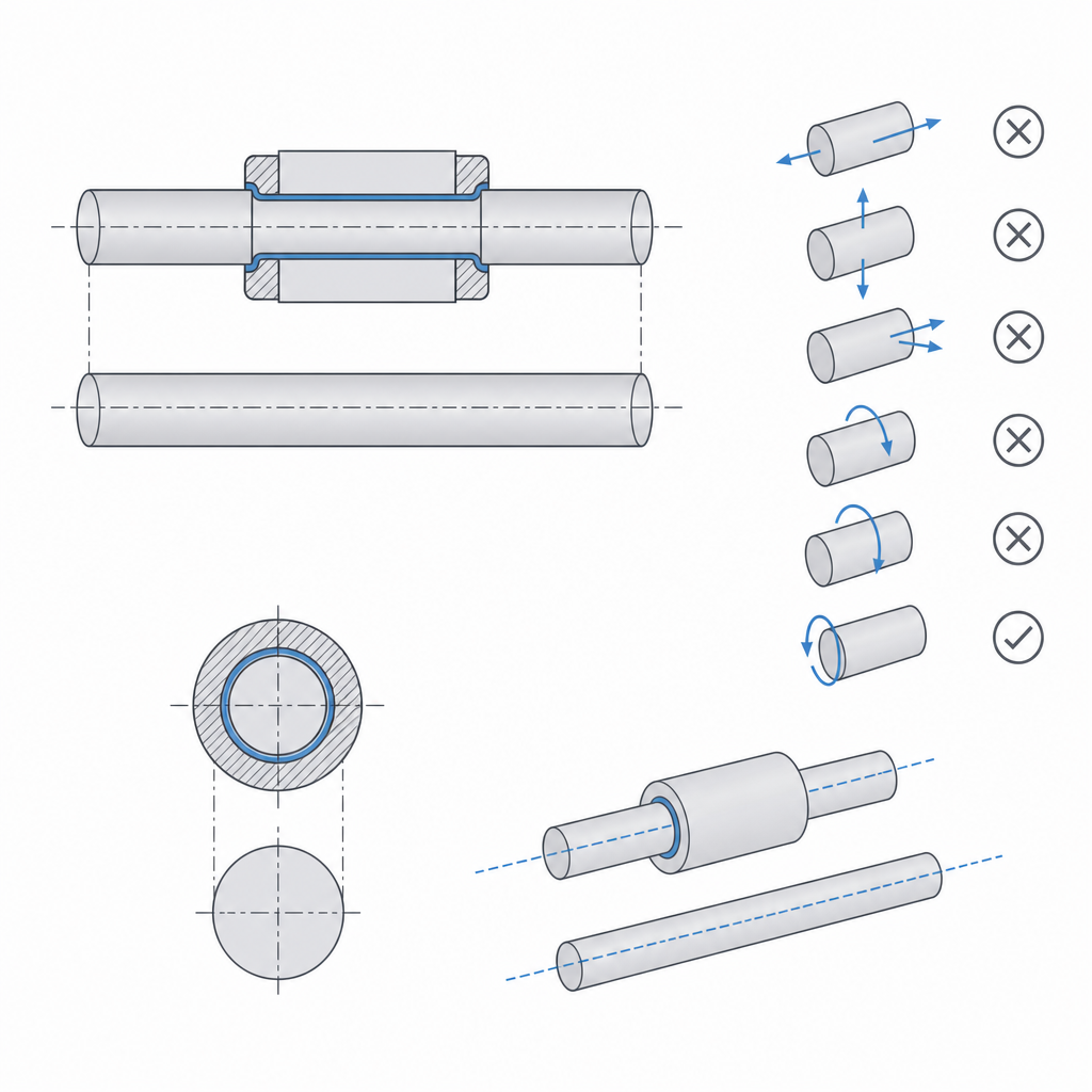
A free body in space has six degrees of freedom: three translations and three rotations. A linear guide exists to remove five of them and leave exactly one, the translation along the axis. That is its entire job, and the bushing is what executes it. By wrapping around the rod, the bushing constrains both transverse translations unconditionally—the carriage can neither drop nor shift sideways. The two transverse rotations, pitch and yaw, are more subtle: the bushing opposes them because its length gives it a lever arm against which the rod bears, but that opposition is not absolute, it is soft, and its stiffness depends on the ratio between the bushing's length and its internal play. A long, snug bushing fixes orientation well; a short bushing—the usual case in FDM parts, where it's barely a few millimeters—leaves an appreciable amount of pitch, because the small radial play multiplied by a short arm turns into a wobble you can feel at the far end of the carriage. That's why, when a single bushing isn't enough, you'll often fit two short bushings spaced apart on the same rod instead of one long one: the separation between them lengthens the arm and stiffens that pitch lock.
The one thing a single bushing cannot prevent in any way is rotation about the rod itself: on a round rod, the carriage is free to spin freely about the axis, like a bead on a wire. That is the physical reason for the second rod. Two parallel rods, gripped by their bushings at some distance from one another, give the carriage a second line of contact, and that distance is the arm that blocks the last rotation. The torque that would roll the carriage is now split into two opposing forces on the two rods, and the carriage is fixed in orientation. The greater the separation between the two rods, the smaller the force each bushing absorbs for the same torque, and the more rigid the guide becomes against loads trying to twist the carriage. That's why a single-rod guide only works when something else prevents the rotation—a second surface, a non-round profile; as soon as the carriage has to hold an orientation on its own, you need both.
Plastic against plastic is not a bearing: it's sandpaper in slow motion
The temptation in FDM is to print the shaft and the bushing together and let them slide. Don't do it if the mechanism is meant to have a service life. Two surfaces of printed plastic in sliding contact are not smooth: they're rows of beads, each a small ridge, rubbing against another set of ridges. The coefficient of friction is high and poorly repeatable, and the worst part is that the softer material—here, usually both surfaces—wears with every pass. Within a few cycles, clearance appears where there used to be a fit, the carriage starts to pitch, and the friction gets worse rather than wearing smooth, because the torn-off particles act as an abrasive.
The real linear guide exists precisely so it doesn't rely on that. A ground steel rod gives you a smooth, hard, straight surface that plastic can't match; a real bushing—sintered bronze, PTFE, or a linear ball bearing—gives you the other half of the tribological pair (the two materials in sliding contact), designed to slide against that steel with low friction and negligible wear. Here it's worth distinguishing the type of bushing, because they don't ask for the same rod. A bronze or PTFE bushing slides well on steel that's merely ground, and the sintered bronze one is also oil-impregnated: it is self-lubricating, and that lubricant reserve is part of why it lasts. A linear ball bearing (LM type) is more demanding: its balls need a hardened and ground rod, surface-hardened to about 58–62 HRC, because on soft steel the balls dent the track (they brinell it) within a few loaded cycles, and the guide ruins itself. In exchange, the ball type swaps sliding for rolling and drops friction to a coefficient on the order of thousandths — though not quite "almost zero," and in fact its breakaway friction, the force that overcomes the first motion thanks to the seals, can be higher than that of a good PTFE bushing at low speed. You pay for that, too, in sensitivity to dirt: the balls need grease and suffer from dust and swarf, and a 3D-printing environment is a dirty one.
The printed part, in this architecture, never touches the working surface: it's the chassis that holds the rod and houses the bushing. That division of roles—steel and bronze do the tribology, plastic does the structure—is what turns a printed guide into a machine and not a prototype that wears out in a few days. Save plastic-on-plastic contact for low loads and few cycles, where smoothness doesn't matter and wear never has time to appear.
Two opposite fits in the same part: clamp the bushing, slide the rod
Here's the mistake that ruins most first attempts: treating the guide as a single fit when it's two, opposite ones, coexisting in the same part. The bushing inside the carriage has to stay fixed—it must not rotate or shift relative to the carriage. The rod inside the bushing has to slide freely, and that clearance is not yours to choose: it's defined by the bushing's manufacturer. A single number can't serve both: if you open it up enough for the rod to slide, you leave the bushing loose; if you clamp it down enough to fix the bushing, that same clamp can close the bushing onto the rod and bind it.
The bushing's housing in the carriage is delicate for a geometric reason: if you clamp it too hard, you deform the bushing inward and rob the rod of the sliding clearance it needed. A thin bronze bushing deforms to an oval with surprisingly little interference—a few tens of microns is enough—and a linear ball bearing is even more sensitive: squeezing the housing deforms its outer sleeve and, with it, the tracks the balls roll on, which raises the preload, binds the rolling, or dents the tracks locally. It doesn't lose some abstract "calibration": it loses the rolling geometry it had from the factory. That's why the housing isn't entrusted to a strong radial clamp. What really holds it without deforming it is a mechanical stop: a shoulder the bushing bottoms against at one end, combined with minimal or zero radial clamp. The bushing goes in, bottoms against the shoulder, and is retained without the wall having to squeeze it. Many cheap LM bearings aren't even press-fit: they go in with a clip or mount in a block-style holder, specifically to avoid touching the sleeve. The underlying reasoning—how to split clearance per side, what closes up and what widens when you print, and why a printed hole comes out narrower than its dimension—is in Tolerances for moving parts, and it applies twice here: once to retain the bushing and once, in the opposite direction, to avoid interfering with the rod's sliding.
| Interface | How it's held or slides | What you're after |
|---|---|---|
| Bushing in the carriage | Axial shoulder + minimal radial clamp | Retain without deforming the bushing |
| Rod in the bushing | Set by the manufacturer, not you | Slide freely, per the bushing |
| Rod support | Clamp or set screw | Hold the rod straight and at its height |
Parallelism is the dimension that decides whether the guide works
With two rods, the critical dimension is no longer a diameter but a relationship: the parallelism of the two rods and the distance between their centers, measured the same at both ends of travel. If the rods don't come out exactly parallel—if they converge, diverge, or aren't at the same height in the two supports—the center distance changes along the axis. And the bushings, which sit at a fixed spacing in the carriage, can't follow that variation: where the rods come closer, the bushings pinch; where the rods spread apart, the bushings go loose. The result is binding: the carriage runs smoothly in one zone and jams in another, and the harder you force it, the more it jams, because the misalignment turns the axial push into a lateral force that presses the bushings against the rods.
This means the precision of a two-rod guide doesn't live in the diameters but in the positions of the supports. And it's two sets of positions, not one: the center distance of the rod supports, and the center distance of the bushing housings in the carriage itself. The two have to match; if either one drifts, you get binding. The two supports have to place their holes at the same center distance, aligned and at the same height, and the carriage has to house its bushings at exactly that same spacing. If you print the parts separately, any drift of the printer between one and the other turns into a loss of parallelism. It pays to print the supports in the same batch and orientation, or better, to tie the geometry so the center distance is fixed by a single reference and not by two independent measurements.
And then there's the orientation of the holes, which hides a real conflict. A hole printed vertically holds its circularity better; one printed horizontally turns oval, because the overhang at the top sags. A rod in an oval hole seats forced or skewed: another direct route to binding. The problem is that in most guides the rod's axis is horizontal, so the support's hole has to be printed lying down, and the "print it vertical" rule can't be applied without standing the whole part on edge. When the axis is horizontal, assume the hole will come out imperfect and give it a remedy: split the hole into two halves along the joining plane, ream it, or open it with a custom-sized drill bit, or replace it with a V-seat and a clamp closing from above. You set the circularity of that seat yourself, afterward — not the printer.
When it's worth it, how far it scales, and how it breaks
A rod-and-bushing guide is the choice when you need an axis of motion that is smooth and precise under moderate loads: the carriage of a mechanism, the axis of a machine prototype, any translation an all-plastic guide wouldn't hold without going loose within a few tens of cycles. Its advantage over the printed alternatives is the smoothness it keeps with use, which is exactly what plastic can't deliver on its own. If your travel is short and the load minimal, a simpler guide is enough and you save yourself the hardware; the moment smoothness, precision, or many cycles come into play, this architecture is the one that delivers.
But it has a physical limit worth not ignoring: the deflection of the rod. A round rod supported only at its two ends sags under its own weight and the carriage's load, and that deflection grows with the cube of the distance between supports: doubling the travel multiplies the bending by eight. Past a certain length, the rod bows in the middle, the carriage sags, and the slide stops being straight. That's why long travels aren't done with an unsupported round rod: either you raise the rod's diameter, or you move to a rail with continuous support along its full length, which holds the line straight where an unsupported rod would already sag. If you promise "long travel," size the rod for deflection, not just for fit.
It has three failure modes, and it pays to keep them as a checklist. The first is binding from over-constraint and a lack of parallelism between the two rods, the most common and the most frustrating because the kinematics are correct and yet the carriage jams: it's fixed at the mounting positions—rod supports and carriage—by letting one interface float, not by opening up the bushings. The second is play and pitch from a bushing that ended up loose in its housing—the carriage wobbles, loses precision, and sometimes rattles; it's fixed with an axial shoulder that retains it without squeezing it, and with two spaced bushings if one short one doesn't give enough arm. The third is rapid wear, the one that shows up when the slide is entrusted to plastic without a real bushing: the printed surface sands itself down, the clearance grows, and the guide degrades on its own. All three share the same underlying antidote: metal where there's sliding, plastic only where there's structure, and the parallelism dimensions treated with the respect they deserve. When you get to housing the bushing or the rod in the part, Embedded hardware: magnets, bearings, and inserts takes you from the type of fit to the concrete geometry of the seat.