Spur gear: the foundation of it all
Two toothed wheels pushing tooth against tooth, turning the rotation of one shaft into the rotation of another: that is a spur gear, and it is the part from which every other gear is built. Before you get into helical gears, planetaries, or worm drives, this is the case you have to master: its kinematics are the cleanest, and its failure modes reappear in every more complex train. The good news is that a well-parametrized spur gear printed in the right orientation is about the most robust thing an FDM machine can produce. The bad news is that getting a single number wrong—the module, the pressure angle, the few tenths of a millimeter of clearance between teeth—is enough to turn two wheels that mesh beautifully on screen into a pair that seizes up or slips in the part.
The gear ratio is a ratio of tooth counts
The first thing a pair of gears does is change rotational speed, and the rule is deceptively simple: the gear ratio is the ratio of the tooth counts. A 40-tooth wheel driving a 20-tooth wheel makes the small one turn twice as fast with half the torque; the factor is exactly 40/20 = 2, and nothing more. It makes no difference whether you think in terms of teeth or pitch diameters, because both are proportional: the pitch diameter is the diameter of the imaginary circle on which two gears roll without slipping, and it is on that circle that the mesh truly happens. The teeth are simply what keeps those two circles from slipping.
Here is a nuance you'll need again when we talk about wear: pure rolling happens only at the pitch point, the exact point where the two circles touch. Away from it, as contact moves along the tooth flank, the flanks do slide over one another. That is why a gear, even when it transmits precisely, keeps filing down its own flanks: sliding is inherent in the tooth's shape, not a manufacturing defect.
That pitch circle is the reference everything else respects. The distance between the centers of two meshing gears is the sum of their pitch radii, exactly that—which is the same as half the sum of their diameters: if you misplace the shafts, the pitch circles stop being tangent and the mesh falls apart—either binding or running with slop. That is why, when you dimension the housing of a reducer, the dimension that matters isn't the outer diameter of the wheels but that center distance.
The module is the shared unit, and it has to match
For two gears to mesh, it isn't enough for their diameters to agree: their teeth have to be the same size, and that size is set by the module. The module is the millimeters of pitch diameter that correspond to each tooth (pitch diameter divided by the number of teeth), and it works like the system's unit of exchange. Two wheels with the same module have teeth of the same pitch and engage; two wheels with different modules simply cannot mesh, no matter how compatible their diameters appear, because their teeth don't land in the same places. A large module means large, thick teeth that carry more load but yield a coarser wheel; a small module smooths the motion but produces finer, more fragile teeth—exactly what FDM handles worst.
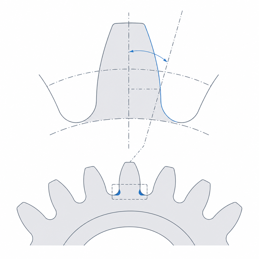
The second number that has to match is the pressure angle, almost always 20°. It is the slope of the tooth flank at the contact point, and it sets the direction in which one tooth pushes the next: part of the force turns the other wheel, and part pushes it away from its shaft. 20° is the industry standard, a reasonable balance between smoothness of mesh and strength of the tooth at the root. The practical point is that it's another compatibility parameter: two gears with the same module but different pressure angles don't match either. The flank has that specific curved shape—the involute—for a functional reason, not a cosmetic one: it is the only profile that keeps the velocity ratio rigorously constant throughout the contact, so the driven wheel doesn't speed up and slow down on every tooth. A poorly drawn profile transmits the rotation in fits and starts; the involute transmits it uniformly.
That separating component—the part of the force that pushes a wheel away from its shaft—isn't a textbook abstraction once you print the housing. It pushes the shafts and bearings outward and, in a printed housing with flexible walls, it tends to open up the center distance under load. Opening the centers increases backlash exactly when you're transmitting the most torque. That is why a printed reducer housing calls for thick walls and ribs between the shaft supports: not to carry weight, but to resist the separating force.
| Parameter | What it is | Rule |
|---|---|---|
| Module (m) | mm of pitch Ø per tooth | Identical on both wheels |
| Pressure angle | Flank slope (involute) | Identical, typically 20° |
| Tooth count (z) | How many teeth the wheel has | Their ratio gives the gear ratio |
| Pitch Ø | m · z | Where they roll without slipping |
| Center distance | (Ø₁ + Ø₂) / 2 | Sets where the shafts go |
The pinion has a minimum tooth count: don't go below 17
The temptation, when you're after a large reduction, is to make the driving pinion as small as possible. But the tooth count has a physical floor you can't ignore. At a 20° pressure angle, below about 17 teeth the cutter—or the theoretical involute—encroaches on the root of the tooth and undercut appears: the base of the tooth is cut away inward, thinned out right at the section that carries the most stress. In other words, the small pinion doesn't just have fine teeth because of the module: on top of that, the geometry undercuts its root—precisely where gears break.
A 20-tooth pinion driving a 40-tooth wheel is perfectly fine: 20 is above the floor. If you need to go below 17, you have two sound options: apply profile correction (shifting the teeth outward to rebuild the root, which your gear generator usually calls profile shift) or raise the pressure angle to 25°, which lowers the threshold at which undercut appears. In FDM, where an undercut tooth is also hard to print cleanly, the practical rule is don't go below 17 without correcting the profile.
Print it flat on the bed
This is where a gear that's correct on paper is won or lost on the printer. A spur gear is printed flat, with the axis vertical, resting on one of its faces. There are two reasons, and both matter.
The first is profile consistency. Printed flat, each tooth is built by repeating the same involute contour layer over layer along its full height, so the flank comes out identical from top to bottom and the two gears contact uniformly. Laid on its side, the tooth profile would be defined by the stair-stepping of the layers and by the overhangs, which would deform exactly the curve the mesh depends on for smoothness.
The second, and more important, is the direction in which the load acts. When one tooth pushes another, the force is tangential: it acts in the plane of the wheel, the XY plane. With the wheel resting on the bed, that force travels along the beads, along FDM's strong direction, and the tooth root—where all the stress concentrates, as in any cantilever beam—is reinforced by layers that run with the load. If you printed the wheel on edge, that same force would pull one layer from the next at the base of the tooth, the weak plane between layers, and the teeth would shear off one after another. This is exactly the reasoning of Layer orientation for motion applied to the most heavily loaded point on the part: orient so the load follows the beads, never so it peels them apart.
Once it's flat, the lever for strength isn't the infill: it's the perimeter. The tangential load at the root is taken by the concentric contours that wrap each tooth, not by the mesh of strands inside. Before you raise the infill, raise the wall count: three or four perimeters give the root a continuous section of material that genuinely works against the force, whereas sparse infill contributes almost nothing there.
Backlash: let the teeth breathe
If you model two gears with perfectly complementary teeth and print them, they won't turn: they'll seize. The reason is the same one that ruins any printed fit: the bead width thickens the walls and shrinkage closes the gaps. Here, the gap that closes is the one meant to sit between a tooth flank and the facing flank of the space it enters. Without clearance, the teeth jam against one another and the torque is consumed by friction instead of moving the load.
That deliberate play between flanks is called backlash, and you get it in two ways: by thinning the tooth slightly relative to its nominal thickness, or by separating the centers of the two wheels a little beyond the theoretical distance. They aren't entirely equivalent, and it's worth knowing why. Thinning the tooth opens the gap between flanks without touching anything else: the involute profile stays intact and contact still passes through the pitch point. Separating the centers, on the other hand, moves contact off the pitch point and reduces the contact ratio (how many teeth are meshing at once), which worsens smoothness and increases sliding and wear. So prefer to model backlash by thinning the tooth; keep center separation as a fallback, for when the wheels are already made and all you can move is the shafts.
Backlash is to a gear what side clearance is to a pivot: a number you don't inherit from theory but design for, allowing for the share the printer will consume. It's the same reasoning as Tolerances for moving parts, carried over from the shaft-hole pair to the tooth-space pair. As there, the exact value depends on your printer and is calibrated; a reasonable starting point is on the order of 0.1–0.3 mm of clearance between flanks, and you tune from there.
The material matters: PLA creeps under sustained torque
Before listing the failure modes, a decision that overrides all of them: what you print the wheel from. PLA is perfect for prototyping the mesh and for gentle or intermittent motion, but it's a poor choice for sustained torque. Its glass transition temperature is around 55–60 °C, and a gear transmitting real torque heats up from flank friction toward that threshold. When it crosses it, the plastic creeps: the teeth yield little by little under load, round off at the tip, and the wheel loses shape without anything having broken. For continuous torque, step up to PETG, ABS, ASA, or, if you want genuine durability, a polyamide (nylon), with or without fiber reinforcement. The rule of thumb: if the gear will bear load for minutes on end, PLA isn't your material.
When the spur gear is the right choice and how it breaks
The spur gear is the default choice whenever you want to transmit rotation between two parallel shafts with a defined ratio: the basis of a reducer, a multi-stage train, synchronized motion between two parts. It's the simplest to model, the easiest to print well, and the most forgiving on an ordinary printer. It's only worth moving to something more complex when you reach its limits: you move to a helical gear when you need a quieter, smoother mesh at high speed, and to a planetary when you want a large reduction in a small volume with the shafts aligned. Bear in mind that the helical gear comes at a cost: its angled teeth generate an axial thrust that loads the shaft in its own direction and calls for a thrust face or an axial bearing that a printed housing rarely has. Before that, the spur gear solves the vast majority of cases.
When it fails, it does so in four ways worth knowing by name. The first and most dramatic is tooth breakage at the root: either because you printed it in the wrong orientation and the base of the tooth delaminated under the tangential load, or because the tooth doesn't have enough section to take the torque—from too small a module, from undercut, or from too narrow a wheel. If you're breaking teeth, check the orientation first; if that's right, the most direct and least costly fix in FDM is to widen the wheel: increasing the face width spreads the same force over a wider tooth without touching the kinematics. Raising the module also adds section, but at equal diameter it reduces the tooth count (m·z = Ø) and can drive you into undercut, so use it as a second option.
The second is seizing from insufficient backlash, which we've already seen: the wheel won't turn or turns in jerks while overheating the motor, and the cure is to open the gap between flanks. The third is flank wear, slow and silent: the inevitable sliding between flanks, made worse by a poor finish—stair-stepped from the layers, with burrs, or over-extruded—files away material on every mesh until backlash widens of its own accord and the torque loses precision. And the fourth, not to be confused with the previous one, is tooth skipping: a one-off overload—excessive torque, or shafts that have flexed apart—lets one tooth slip over the next instead of pushing it. Wear is gradual and measured in lost precision; skipping is abrupt and warns you that the torque exceeds what the mesh can take or that the housing is yielding. A clean, well-calibrated profile doesn't just mesh more smoothly: it lasts much longer.
With these parameters agreeing, the wheel flat on the bed, and the material chosen for the load, you have the gear solved. The next step is making sure the orientation you chose for the teeth fits with the rest of the mechanism: Layer orientation for motion takes it from the tooth to the whole part.