Real-world printed clearances
You have decided the fit family from the joint's function (see Choosing fits: clearance, transition, interference). Now you need a number — the actual gap, in millimetres, to model between the two parts. Get this right and a lid clicks on, a pin slides, a bearing seats with a satisfying push. Get it wrong by a tenth and the same lid either rattles or won't go on at all. These are the numbers that work on a typical 0.4 mm nozzle, and how to dial in your own.
The numbers that work
A "clearance" here means the total diametral gap — the difference between hole and peg diameter, or the gap on each side of a slot. Model it by enlarging the hole, shrinking the peg, or splitting the difference between the two parts.
| Fit | Total clearance | Feels like |
|---|---|---|
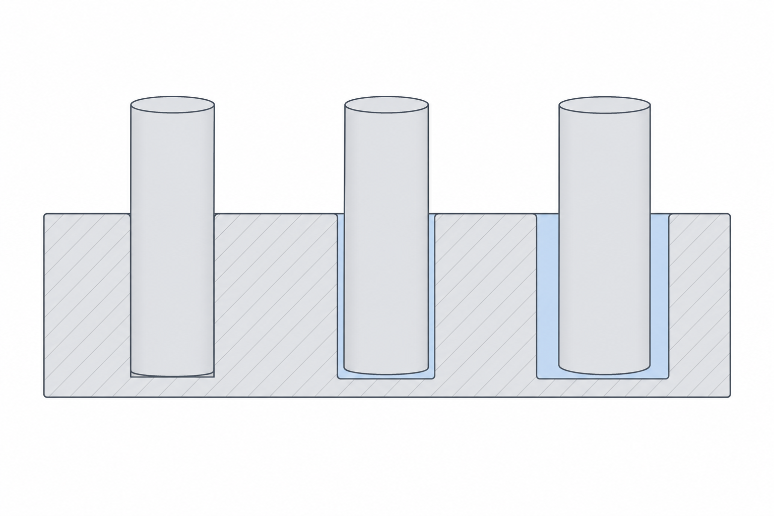
| Press / interference | 0.00 to −0.05 mm | driven in, stays forever |
| Snug / locating | 0.10–0.20 mm | pushes together, holds, comes apart by hand |
| Free / sliding | 0.30–0.40 mm | slides freely, no force |
| Loose / generous | 0.50 mm+ | sloppy on purpose, dirt-tolerant |
A negative number means the peg is bigger than the hole — true interference. For a printed press fit, 0.0 to −0.05 mm is usually enough, because the printer's own error already eats into it. Start at the middle of each band and adjust from there.
Material changes the number
PLA is stiff and dimensionally honest, so the table above is calibrated for it. Other materials move the target.
- PETG is slightly gummy and tends to print a touch oversized, with more ooze and stringing into gaps. Add roughly 0.05 mm of clearance over your PLA number for moving fits, and don't trust a tight press fit to stay — PETG creeps under load.
- ABS / ASA shrink more as they cool, so holes close up and pegs pull in. Parts come out a little smaller overall. Expect to add clearance for sliding fits and to re-tune press fits, because the shrinkage is part-size dependent.
- TPU and other flexibles are forgiving by nature — a snug fit becomes a press fit, and a press fit may simply not assemble. Go looser than you think.
Why holes shrink and pegs grow
There is a reason printed parts skew tight in exactly the direction that ruins fits: holes come out undersized and pegs come out oversized. The cause is mostly geometric and is covered in depth in Holes, pegs and first-layer squish — the short version is that a vertical hole is approximated by flat chords that cut inside the true circle, and that extruded plastic bulges slightly outward at every edge. Both effects steal from your gap.
Calibrate your own number
The table is a starting point, not gospel — your printer, your filament, your slicer settings and even your room temperature shift it. Don't design a ten-part assembly around a guessed clearance. Print a test first.
The standard move is a small clearance comb: a row of holes (or pegs) where each one steps the gap by 0.05 mm — say 0.05, 0.10, 0.15, up to 0.40 — all printed in one go. Try the mating part in each and find the first one that behaves how you want. That value, for that material on that machine, is now your house number for that fit. The full method, including how to make the coupon and record results, is in Test coupons and calibration.
Do this once per material and write the numbers down. From then on you are designing with measured clearances instead of hoping, and parts start fitting on the first print.