Friction hinge: holds at any angle
A laptop screen stays where you let go of it: at 100°, at 130°, wherever, and it holds the weight of the lid there with no stop to catch it and no spring to support it. That's a friction hinge, and its single job is to generate a resisting torque that beats the torque the weight is trying to impose on it. No detents, no marked positions: just continuous holding across the whole travel. Printing one that works is easy. Printing one that still works six months from now is the real problem, because plastic-on-plastic friction is exactly what ages worst in an FDM part.
The friction torque has to beat the weight torque
A friction hinge is a balance of moments, and it pays to frame it that way before you touch a single diameter. The moving part — the lid, the arm, the stand — hangs off the pivot with its center of mass some distance from the axis. That mass, multiplied by its horizontal lever arm, generates a torque that tends to swing the hinge downward. For the part to stay put, the friction torque at the pivot interface has to be equal to or greater than that weight torque in the worst-case position.
And the worst-case position isn't the one you'd guess. The weight torque isn't constant through the swing: it depends on the sine of the angle between the vertical and the vector running from the axis to the center of mass. It's at its maximum when that axis-to-center-of-mass vector is horizontal — the mass right out to the side of the axis — and it falls to zero when that vector points straight up or straight down. Watch out: that angle is not the angle of the lid. A lid opened to 120° can still have its center of mass far from horizontal, depending on how you distribute the mass; the worst case is the horizontal arm, and which lid opening that lands at is decided by your geometry, not generically by 90°.
Always size for that worst case if your range of use passes through it. If the hinge travels through the horizontal-arm position, calibrate there and it'll hold everywhere else with plenty of margin. But if the useful range never puts the arm horizontal — a lid that only operates between 95° and 135°, with the center of mass already past vertical — calibrating for the theoretical maximum oversizes it and seizes it up for no reason. Size for the maximum moment within the travel you actually use.
The friction torque, for its part, comes out of the product of three things: the normal force with which the surfaces press against each other, the coefficient of friction of the pair of materials in contact, and the radius at which that friction acts. All three are design levers. The one you control most finely is the normal force, and you generate it in one of two ways.
Two ways to generate the normal force
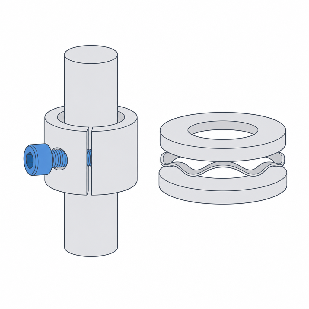
The first is an interference fit between shaft and hole: you make the shaft a hair thicker than its housing, so that the hole wall is permanently strained outward and grips the shaft all the way around its contour. That circumferential tension is the normal force, and the friction it generates as it turns is the resisting torque. Here the friction is radial, spread over the cylindrical surface of the shaft, so its lever arm is the shaft radius. It's the simplest solution — no extra parts — but also the least adjustable: once it's printed, the torque is what it is and depends entirely on your having nailed the interference at print time.
The second is to clamp a split bushing against the shaft with a screw, or to insert a wave washer that pushes axially on the faces of the joint. Here the normal force isn't fixed by the printed geometry but by the clamp, and that changes everything: you can tune the torque by turning a screw until the hinge feels the way you want, and retighten it when wear loosens it. A slotted, springy bushing closes onto the shaft as the screw compresses it, and its friction is still radial on the shaft. The wave washer works differently: it clamps two flat annular faces against each other, so its friction is axial and its lever arm isn't the shaft radius but the mean radius of the contact ring, usually quite a bit larger. That gives it more torque per unit of normal force, but it obeys a different law — that of a disc clutch, not a bushing — so it's worth keeping them separate in your head. It's more parts and more assembly, but it's the difference between a hinge that's born calibrated and one you recalibrate by hand.
The friction that holds isn't the friction that moves
There's a subtlety that decides whether a hinge that "holds" really holds: static friction is greater than kinetic. It takes more to start the motion than to keep it going. A hinge calibrated right at the limit can stay locked while it's at rest and yet slide on its own once something sets it in motion — a knock on the table, a shove from closing the lid next to it — because as it goes from static to kinetic the friction torque drops a step and suddenly it no longer beats the weight. Calibrate against the dynamic case, not the static one: make the hinge hold even after you've moved it, not just when it's been sitting still for a while.
The clearance goes the opposite way from a free joint
Here's the mental flip that's hardest, especially if you're coming from designing pivots that have to turn smoothly. In a normal joint you want gap: you make the hole larger than the shaft so it spins freely without seizing. In a friction hinge you're after exactly the opposite: you want them to rub, and to rub with a specific force. The dimension that in another mechanism would be a defect — the shaft not going in with clearance — here is the spec.
The fit you're after lives on the border between transition and light interference: neither the sliding gap of a hinge knuckle nor the outright interference of a press fit, but the exact point where the surfaces touch, pressing just enough to brake but not so much as to lock. As a starting value in PLA or PETG, aim for a transition-to-light-interference fit on the nominal diameter: on the order of zero to 0.15 mm of diametral interference, calibrated for the torque you need and not for the shaft to slide in comfortably. Sweep that range in steps of about 0.05 mm — three or four coupons are enough to bracket the point — because the entire useful window fits in a couple of tenths and a coarser step jumps right over it.
And like any tight fit in FDM, it has to be budgeted against the measured part, not against the nominal dimension. A printed hole comes out narrower than you drew it and a shaft comes out thicker, so the real interference is already greater than the one you drew, even before you add any extra clamp. That same physics governs any press fit, and you have it worked out in Interference without cracking; the method for measuring your real clearance and turning it into reliable dimensions is in Tolerances for moving parts. A friction hinge is nothing more than an interference fit you've decided to let turn.
| Lever | Effect on torque | Note |
|---|---|---|
| Shaft/hole interference | Raises torque with the clamp | Fixed at print time; 0–0.15 mm on Ø, budget against the measured dimension |
| Split bushing + screw | Radial torque, adjustable and re-tightenable | Compensates wear by turning the screw |
| Wave washer (axial preload) | Axial torque on the mean face radius | Larger arm than the shaft; clutch law, not bushing law |
| Shaft radius | More radius, more torque for the same force | Lever arm of the radial friction |
| Contact length | Raises torque and spreads the pressure | At the same interference, more strained area: more torque and less local wear |
Wear is the failure that doesn't forgive
A plastic-on-plastic friction hinge works on day one and dies a little with every turn. The friction that gives you the torque is the same friction that tears material off the contacting surfaces: each cycle polishes the shaft and the hole a little, the fit loosens, the normal force drops, and the torque falls. What held fixed at 120° on day one starts sliding on its own after a few hundred cycles. That's why bare plastic only works for short-lived or low-cycle friction hinges; if the part is going to open and close daily for years, plastic on plastic isn't the answer.
On top of this there's a faster, cruder settling at the start: the first few dozen cycles flatten the layer ridges on the contact surface, and a freshly calibrated hinge loses torque disproportionately in its first uses before it stabilizes. It's common practice to "break in" the hinge a few times and retighten then, once that initial settling has passed and the torque has settled at its steady-state value.
The deep fix is not to trust the friction interface to two printed plastics. Embedding a component meant to rub — a metal bushing, a friction washer, a bronze or nylon bushing — moves the contact to materials that take the rubbing without polishing away, and leaves the printed plastic as mere supporting structure. But choose the bushing material knowing what you're asking for: a metal or bronze bushing brings surface durability without losing friction, whereas nylon slides very smoothly and lasts, but has a low coefficient of friction — exactly the opposite of what you need to hold — so with a low-friction bushing you'll have to raise the normal force to recover the torque the material takes from you. The procedure for housing those components with just the right pressure, without cracking the part as you insert them, is the same as for any insert and you have it in Interference without cracking. A well-chosen bushing turns a short-lived hinge into a long-lived one without changing the geometry around it.
On top of this there's a second torque thief, slower but just as sure: creep. Plastic loaded continuously flows slowly to relieve the stress squeezing it, so the interference that generated the normal force relaxes over the months even if the hinge hasn't moved. PLA is the stiffest and the best at holding position in the short term, but every thermoplastic creeps to some degree. A wave washer defends against this better than a rigid interference, because its elastic preload has travel left to keep pressing even as the dimension gives up a few tenths: it doesn't deliver all the torque at once, and so it doesn't lose it all at once either. That said, that elastic travel is modest — fractions of a millimeter — so it compensates for creep of a few tenths, not a severe settling of millimeters; past its travel, the washer runs out of clamp too.
Calibrate it like any tight fit
No table will give you the exact diameter for your torque, because it depends on your material, your nozzle, your flow calibration, and the specific weight hanging off the pivot. The serious path is the same as for any interference fit: print a series of shafts with stepped interferences in the same hole — or of housings over the same shaft — in steps of about 0.05 mm, assemble them, and try by hand which one stays locked in the most demanding position without taking an annoying amount of effort to turn. That's your diameter. Note it down and reuse it as long as you don't change material or nozzle.
Two conditions for the number to be valid. Orient the coupon the way the final part will go: a shaft printed standing up on the bed has its seam running around the contour, and the friction contact is distributed differently than on one printed lying down. A hole printed vertically comes out more cylindrical than one printed lying down — it dodges the ovaling and the overhang sag — but in exchange it comes out somewhat undersized and slightly faceted from the layer resolution, and that undersizing is exactly what throws off a friction dimension if you don't measure it. And reuse the number only across similar diameters, because the relative weight of the bead error changes with the pivot size. Within that, the number transfers.
If what you need isn't continuous holding but for the hinge to stay at marked, specific positions — closed, at 90°, fully open — the mechanism is a different one: there you want detents that snap into each stop, not uniform friction across the whole travel. But for "let go of it wherever you want and have it stay," the balance of moments in this article is all there is: friction torque against weight torque, calibrated at its most demanding position and defended against wear. When you generate that torque with a shaft pressed into its housing, it pays to have well internalized the physics of the clamp that Interference without cracking lays out.