Flexible couplings and clutches: beam, bellows, cone, friction, centrifugal, and limiter
Two shafts that ought to be perfectly aligned never are. A motor that settles crooked on its screws; an output shaft that ends up half a millimeter off-center; a printed part that warps as it cools: any of these leaves the two shafts with their center lines crossed or offset. Join them with a rigid sleeve and that misalignment turns into a side load that grinds at the bearings until something gives. A flexible coupling exists for exactly this: to carry the rotation of one shaft to the other without carrying along the mounting error. A clutch does something different but related: it decides when and how much torque passes from one side to the other. Both families solve the same underlying problem—how to connect two rotations without making the connection a rigid tie—and in FDM both run into the same three limitations: the anisotropy between layers, the wear of the surfaces that rub, and the drift of any threshold that depends on printed geometry.
The beam coupling: stiff in torsion, soft in bending
The beam coupling is the most elegant solution in the catalog. You start from a solid cylinder and make one or more helical cuts that wind around without ever closing, leaving one continuous thread of material that climbs in a spiral. What you end up with is a part that behaves two ways at once depending on how you load it. In torsion it responds stiffly: twisting the cylinder in the direction of rotation loads the cross section of the helical thread in combined torsion and bending—not in contact between coils, which never quite touch under normal torque—and that resisting section is what keeps the lag between input and output almost at zero. In bending and lateral offset, by contrast, it responds softly: the helix behaves like a spring, each coil yields a little, and the assembly absorbs the shafts' misalignment without sending that load back to the bearings. It's worth knowing that the torsional stiffness isn't perfectly symmetric: in one direction the cut tends to close and in the other to open, so the coupling is somewhat stiffer in one direction than the other.
Zero lost motion—zero backlash, which is exactly what you want if you're going to reverse the direction of rotation—isn't a property of the helix; it comes from the coupling being a single part. Any monolithic printed coupling comes off the bed already possessing that property, and that's its advantage over a jaw coupling or an Oldham, which do carry play in their contacts. What the helix does add is separating the two stiffnesses: hard in torque, soft in misalignment.
The kinematics are those of a torsional spring with its own axis. The torsional stiffness is set by the width of the material thread you leave between cut and cut and by the pitch of the helix: a wide thread and a short pitch give you more stiffness and more torque capacity, but less tolerance to misalignment; a thin thread and many turns give you more flexibility and the ability to absorb more total angular misalignment—it's spread across more coils—but with less torque before the thread yields. This isn't a free choice: it's the central trade-off of the part, and it separates two distinct limits—the torque it transmits and the maximum misalignment it tolerates without permanently deforming the thread. You resolve it by weighing how much misalignment you expect against how much torque you have to pass.
The advantage of printing it is that it comes out as a single part, already assembled (print-in-place), with nothing to put together, because the helical cut is the only gap and there are no two bodies to separate. The trap is orientation. If you print the cylinder standing up, the helical cuts get spread layer by layer and the thread of material that acts as the spring crosses dozens of layer lines; each coil is then a weld between layers working in tension when the coupling flexes, and that is exactly the weak plane of an FDM part. The coupling doesn't break through the plastic: it delaminates along one of the thin cuts and the helix unzips. The defense is the same one that governs any printed mechanism—orient so the load follows the beads rather than peeling them apart—and it's worked out in Layer orientation for motion.
The bellows solves the same need with a different geometry: instead of a cut helix, a corrugated wall folded like an accordion that contracts and extends. At absorbing misalignment it's even more flexible than the beam because each wave yields like a fold, but that same flexibility makes it softer in torque, and its thin walls are the most prone to delaminate of the whole family. In FDM it's in fact the worst candidate on the list: a corrugation of one or two perimeters barely holds any torque, and the lower waves require support that then fouls the functional face. It serves when misalignment is large and torque is low; for high torque and small misalignment, the beam responds better.
The friction clutch: transmitting torque while allowing slip
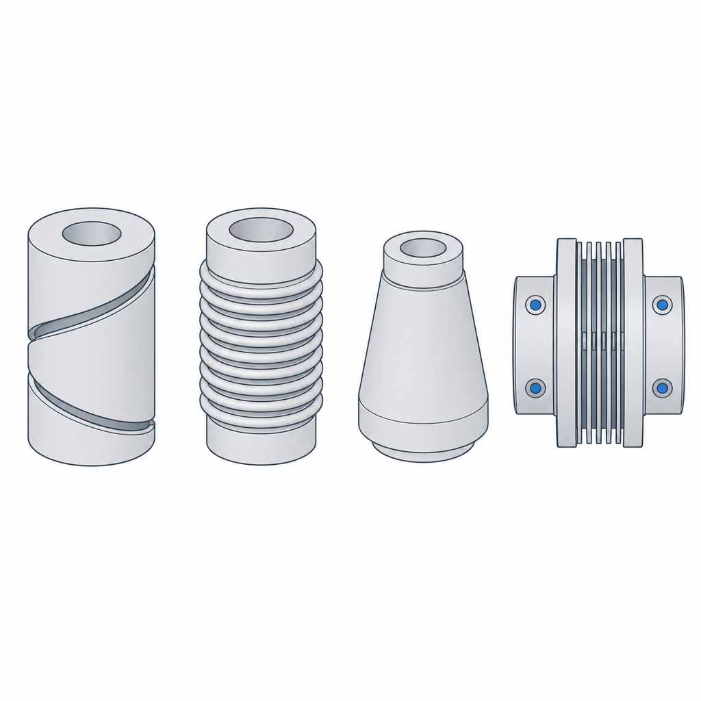
A friction clutch transmits torque through the rubbing between two surfaces you press against each other. The cone form mates a male cone into a female one and the axial pressure squeezes them together; the disc form stacks several alternating surfaces and compresses them. In both cases the torque they can pass is the product of the force with which you press, the coefficient of friction of the surfaces, and the effective radius of the friction ring—that intermediate point between the inner and outer edge of the ring where the contact really happens, not a single radius. Raise any of the three and more torque passes.
The two forms are not equivalent for the same axial force. The cone multiplies the torque because the normal force on the faces is not the axial one: it's the axial force divided by the sine of the cone's half-angle, so the tighter the cone, the more normal force for the same pressure and the more torque. That is its reason for being against a flat disc. The disc clutch multiplies in a different way: each pair of faces in contact adds its own friction interface, so with several discs the torque scales with the number of interfaces, not with the area—area doesn't enter into Coulomb friction. Stacking discs is a way to pack many interfaces into little axial space.
What makes a friction clutch useful—and what sets it apart from a rigid coupling—is that it lets you couple two sides turning at different speeds. While the surfaces slip over each other, the clutch transmits torque but lets the speed difference burn off, until both sides synchronize and stop slipping. That slipping phase is what lets you start a heavy load smoothly without an abrupt jerk, and it's also what modulates: ease off the pressure and the clutch slips sooner and passes less torque.
The problem in FDM is that same phase. A printed friction track isn't made for rubbing, and the dominant failure isn't always the one it appears to be. The heat of rubbing degrades the surface unpredictably—sometimes it polishes it and changes the grip, sometimes it provokes a juddering stick-slip—but the mechanism that really kills a PLA track is thermal: with a glass transition temperature of barely 55–60 °C, the heat of slipping softens the plastic well before melting it, and the track flows and deforms under pressure at a low temperature. On top of that comes abrasive wear, which files away the geometry of the contact. A printed friction clutch is therefore a good demonstration of the principle and a decent torque limiter, but a poor clutch for continuous service: each slipping cycle eats a little of its capacity. If you need it to last, the track needs a wear-resistant material or, better, a friction pair where at least one of the two faces is not printed plastic.
The centrifugal clutch: engaging as the speed rises
The centrifugal clutch is actuated differently. You don't actuate it by pressing: it's actuated by the rotational speed. A set of shoes mounted on the input shaft is held inward by a spring. As the revolutions rise, the centrifugal force on each shoe's mass grows with the square of the speed, and as soon as it overcomes the spring, the shoes swing outward and grip by friction the inner face of a drum tied to the output shaft. Below that regime, the motor turns essentially free; above it, the clutch is engaged. That's why chainsaws and karts use it: the engine can idle without stalling because at idle the clutch is released, and it engages only when you open the throttle.
That transition is not a clean on/off. Just below the engagement regime, there's a band of partial slip in which the shoes already rub lightly before gripping fully, and that's where a printed centrifugal clutch generates the heat that glazes and deforms its track—the same friction problem as before. And there's hysteresis: the clutch engages at one regime but disengages at a lower one, because once the shoes are open the moment arm of the centrifugal force changes and the friction itself helps hold them out. Account for it when designing, or the clutch can stay stuck at idle.
The kinematics put the engagement regime in the hands of two numbers: the mass of the shoes and the rate of the return spring. More mass or a softer spring: it engages at fewer revolutions. Less mass or a stiffer spring: it engages at more. That pair of values is what you design, and it's also where FDM imposes its constraint: a printed shoe weighs only as much as the plastic it's made of, which is very little. Since the centrifugal force is mass times speed squared times radius, before adding mass to a shoe with little room to spare it usually pays more to move the mass away from the center: pushing the radius is the lever real centrifugal clutches lean on most. And here a real embedded metal spring, rather than a printed one, pays for itself in reliability, because a plastic spring relaxes its force over time and shifts the threshold on its own. The criterion for when to embed hardware instead of printing it is covered in Embedded hardware: magnets, bearings, and inserts.
The torque limiter: slipping on purpose to protect the mechanism
The limiter (slip clutch) uses the same friction physics as the cone clutch, but with the intent reversed. You don't want it to transmit always: you want it to transmit up to a maximum torque and slip beyond that. While the working torque stays below the threshold, the limiter behaves like a rigid joint and passes all the rotation; the moment something jams and the torque spikes, the surfaces slip and the excess torque never reaches the fragile part of the mechanism. It's the mechanical fuse of a printed gear train: faced with a lockup, you'd rather a friction track slip than have a PLA tooth blow out.
There are two ways to set that threshold. One is spring-preloaded friction: you press two faces together with a calibrated axial force, and the slip torque is that force times the friction times the radius, just as in the cone clutch. The other is elastic detents—teeth that seat into their pockets and that, when the torque is exceeded, jump out of their seat with a click and let the part turn; here the threshold is set mostly by the angle of the tooth's ramp: a 45° flank trips at a very different torque than a 30° one with the same preload, which is why that angle is the main design variable of the detent, along with the force that keeps it seated. The spring version slips continuously and quietly; the detent version warns you with a chatter, which is sometimes an advantage because you hear that the mechanism has reached its limit.
In FDM the limiter is among the clutches that fit best, precisely because slipping is its function and not an accident: you don't ask it for continuous service, only to act at the moment of the jam. Even so, it shares the Achilles' heel of everything that runs on printed friction: every time it slips, it glazes and wears the track or files down the detent, and the threshold drifts—usually downward. That drift isn't measured in months but in slip events: a limiter that never trips doesn't drift, and one that trips a hundred times a day goes out of calibration in a week. For example, a track that trips at 2 N·m today may fall to 1.5 N·m after a few thousand trips. If a metal spring provides the preload and a resistant material the track, that drift slows down a great deal.
| Part | What it does | Design variable | FDM failure mode |
|---|---|---|---|
| Beam coupling | Absorbs misalignment without backlash | Thread width and helix pitch | Delamination of the thin cuts |
| Bellows | Absorbs large misalignment, low torque | Number and thickness of corrugations | Fracture of the thin wall |
| Cone clutch | Transmits torque, allows slipping | Clamping force, half-angle, radius | Glazing and loss of torque |
| Disc clutch | Transmits torque in little axial space | Number of interfaces, clamping force | Disc warping; uneven pressure distribution |
| Centrifugal clutch | Engages above a regime | Shoe mass and radius, return spring | Plastic spring that relaxes the threshold |
| Torque limiter | Slips above a maximum torque | Spring preload or detent ramp angle | Threshold drift from wear |
The three FDM limitations in one view
If you look at the whole family, the failure modes boil down to three, and it's worth keeping them all in view at once because almost any design runs into more than one.
The first is the delamination of the thin cuts in the elastic couplings. The helix of a beam and the wall of a bellows are thin because they have to be flexible, and that same thinness leaves them at the mercy of the bond between layers if the orientation is bad. The cure is one of orientation, not of thickness: get the section that flexes to work along the beads. When the geometry forces you into a compromised orientation, the adjustment that buys the most interlayer adhesion is turning down the part cooling fan over that zone; raising the extrusion temperature a few degrees and reducing the speed help too, but cooling is the lever with the greatest effect.
The second is the glazing and loss of torque on any printed friction track. Plastic isn't a good dry-friction material: it rubs, heats up, and degrades, and in the case of PLA its glass transition is so low—55–60 °C—that the track softens and flows with the heat of slipping well before melting. That's why continuous-service friction clutches are the worst candidates to print as is, and why the limiter—which only rubs at the instant of the jam—is the best. Where the friction is essential and continuous, the honest answer is not to trust it all to plastic: a metal face, a filled wear-resistant material, or accepting that the part is only a demonstration.
The third is the drift of the threshold. Anything that depends on an engagement or slip point—the regime of the centrifugal clutch, the torque of the limiter—is calibrated against a geometry and a force that wear moves. Surfaces get filed down, plastic springs flow and relax their force, and the design value shifts with use. Embedding a real metal spring freezes the part of that value that depends on the spring; a wear-resistant track material handles the other half. And since every tenth of clearance in the tracks and detents changes both the engagement torque and the wear, all of this rests on getting the fits right first: how much gap you leave between the parts that rub and seat is the basis for any of these thresholds being repeatable, and that's governed by Tolerances for moving parts.